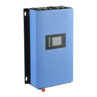
4.1. The installations of the GTIL system are shown above,The ac plug can either
connect to the nearby AC socket or plug into the limiter socket,the dc signal cable can
reach max 30 meters longth so that you can able to install the inverter far away from the
limiter module.The ideal installation is that the limiter install near the GTIL. The GTIL
unit and the Limiter Module are placed close to each other. The signal wires will be
short, as supplied with the unit.
4.2. Use a dedicated 20 A breaker for the GTIL in the Load Circuit breaker panel board
4.3. Wiring and Connection Procedure
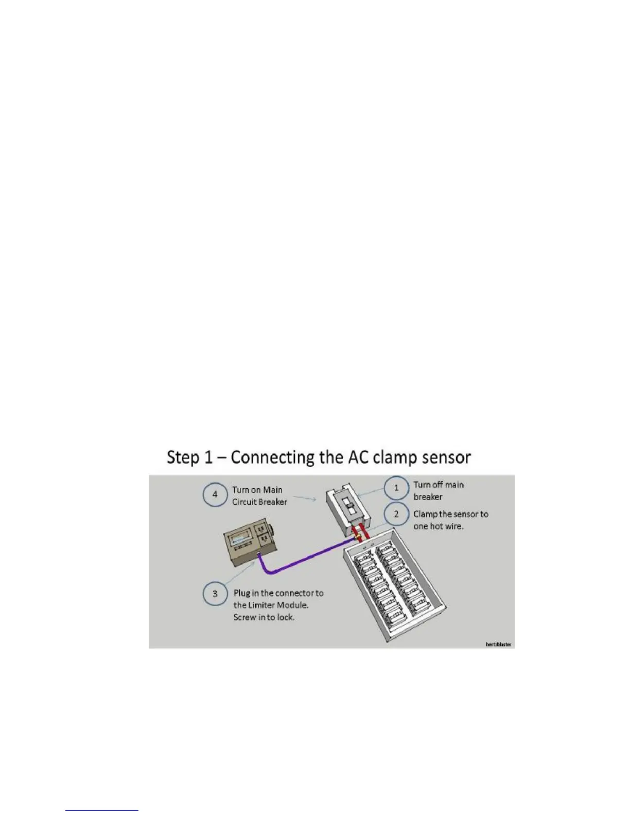
4.3.1. After the GTIL and LM are properly installed. Shut off the main circuit
breaker. Connect the clamp sensor to one hot wire after the main breaker.
Connect the other end of clamp sensor signal cable to the LM. Neatly lay out the
signal cable. You can now safely open the Main breaker.
4.3.2 Connect the LM module to grid. Using the terminal block, use at least wire no.12
AWG (20A ampacity - wire not included in the package) and connect to 20A circuit



 To Next Page