Do you have a question about the Master Bilt VOAM 48-79 and is the answer not in the manual?
Explains safety-alert symbols and defines signal words (DANGER, WARNING, CAUTION, NOTICE).
Safety warning about servicing electrical components and using qualified technicians.
Guidelines for loading product to ensure proper air flow and prevent blocking grilles.
Describes display indications during normal operation, alarms, and info menu.
Identifies causes for high head pressure, such as clogged coils or defective fans.
Lists potential causes for low back and head pressure, like restrictions or low refrigerant.
Outlines reasons for a warm cabinet despite normal pressures, like frost or air screen issues.
Details potential causes for coil blockage due to frost or ice.
Troubleshooting steps when the compressor cycles on overload.
Electrical wiring diagram for models with 115V LAE AT2 control.
Electrical wiring diagram for models with remote 115V LAE AT2 control.
Electrical wiring diagram for vertical open air merchandisers with 220V LAE AT2 control.
Electrical wiring diagram for Canada-only cabinets with 115V LAE AT2 control.
| Model | VOAM 48-79 |
|---|---|
| Refrigerant | R-404A |
| Phase | 1 |
| Lighting | LED |
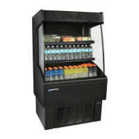
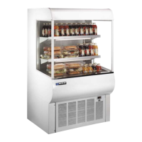
| Type | Vertical Open Air |
| Height | 79.00 inches |
| Voltage | 115 |
| Hertz | 60 Hz |
| Door Type | Open front |
| Certification | UL |
| Category | Merchandisers |