Assembly
and
adjustments
(continued)
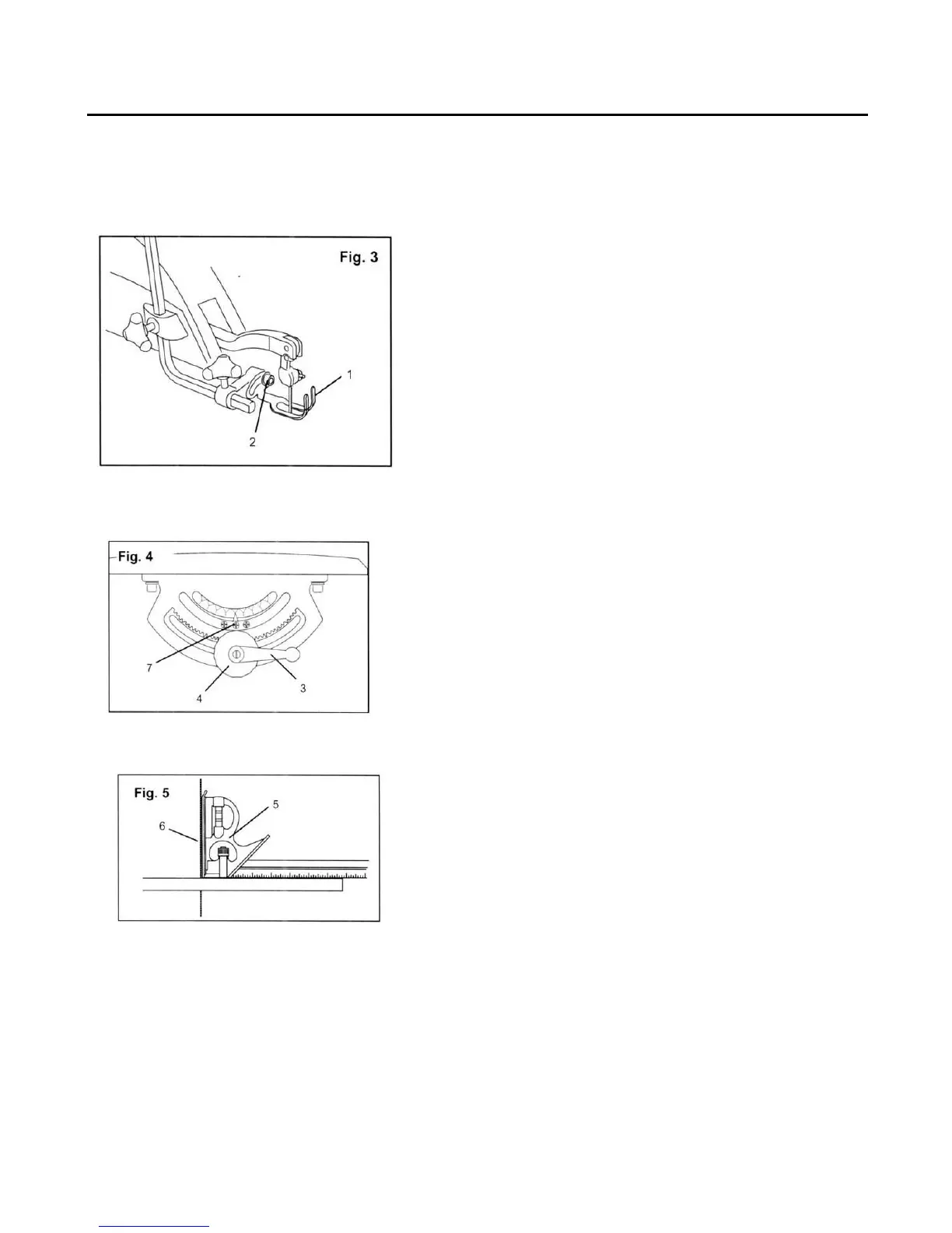
Align the bevel indicator (Fig. 3-5)
The bevel indicator has been factory adjusted, it should be rechecked prior to use for best
operation.
1. Remove the blade guard foot (1) using a hex key
to loosen the screw (2).
2. Loosen the table bevel lock handle (3) and turn
the table adjustment knob (4) to move the table
until it is approximately at a right angle to the
blade.
3. Use a combination square (5) (not provided) to
set the table exactly 90º to the blade (6). If there
is space between the square and the blade adjust
the table angle until the space is closed.
4. Tighten the table bevel lock handle (3) to prevent
movement.
5. Loosen the screw (7) holding the bevel scale
pointer and position pointer to 0º. Tighten the
screw.
6. Attach the blade guard foot (1) and tighten the
screw (2).
240-0041 (888)315-3080 11