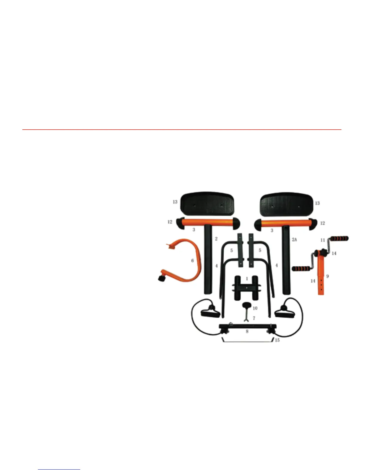
DIAGRAM OF PRE-ASSEMBLED PARTS
Once you open your Master Gym® box you will see your product
pre-assembled as shown in the illustration below.
1 Frame
2 Rear support tube
2A Tube with a loop for the stretching rubber bands
3 Base bars already attached to the support tubes (2 and 2A)
4 Swing tubes
5 Backpedals
6 Handlebar and roller strip holding tube
7 Wing nut
8 Roller strip and stretching rubber bands
9 Handlebar height adjustment tube
10 Frame Knob
11 Handlebar knob
12 Non-slip rubbers assembled to the base bars
13 Non-slip pedals
14 Handlebar
15 Steel bar
NOTE: The images and diagrams in this manual are for reference
only. The actual appearance and technical parameters are
subject to change without previous notice.