´3('(67$/)$10$&3'')%
© 2015, Pinnacle Products International, Inc. 15 +9)$LU&LUFXODWRU8VHU¶V0DQXDO
1(9(5/($9($)$1
81$77(1'(':+,/(
23(5$7,1*25:+,/(
&211(&7('72$32:(5
6285&(
,QVWDOODWLRQDQG$VVHPEO\
7RROV1HHGHG:
Pliers
3KLOOLSVKHDGVFUHZGULYHU
)ODWKHDGVFUHZGULYHU
PPDGMXVWDEOHZUHQFK
3DUWV,QFOXGHG,Q%R[:
%DVH
)URQW*XDUG
5HDU*XDUG
0RWRU$VVHPEO\
)DQ%ODGH$VVHPEO\
/RFNLQJ&ROODU
8SSHU6XSSRUW3ROH
/RZHU6XSSRUW3ROH
1. Place the base on level ground
2. Mount the support pole to the base. Make
sure the holes line up.
3. Secure tightly with 5 flange screws using the
wrench.
4. Put down the base cover.
5. Loosen the locking collar screw using the
Allen wrench (hex wrench). Extract the upper
support pole slowly to adjust the height of the
fan.
6. Mount the motor assembly to the connector
on the upper support pole. Make sure the
holes line up
7. Secure motor assembly with Bolt (M12*40)
and Nut (M12). Tighten the bolt firmly using
the wrench.
8. Slide the rear guard on to motor assembly
and secure it with 4 flange screws. Tighten
the screws firmly using the wrench.
9. Loosen the screw on the back of the fan
blade assembly using the Allen wrench (Hex
Wrench). Slide the fan blade assembly onto
the motor shaft.
10. Attach the front guard to the back guard and
secure with the fasteners on the front guard.
127(7KLVPRGHO&$1127EHZDOOPRXQWHG
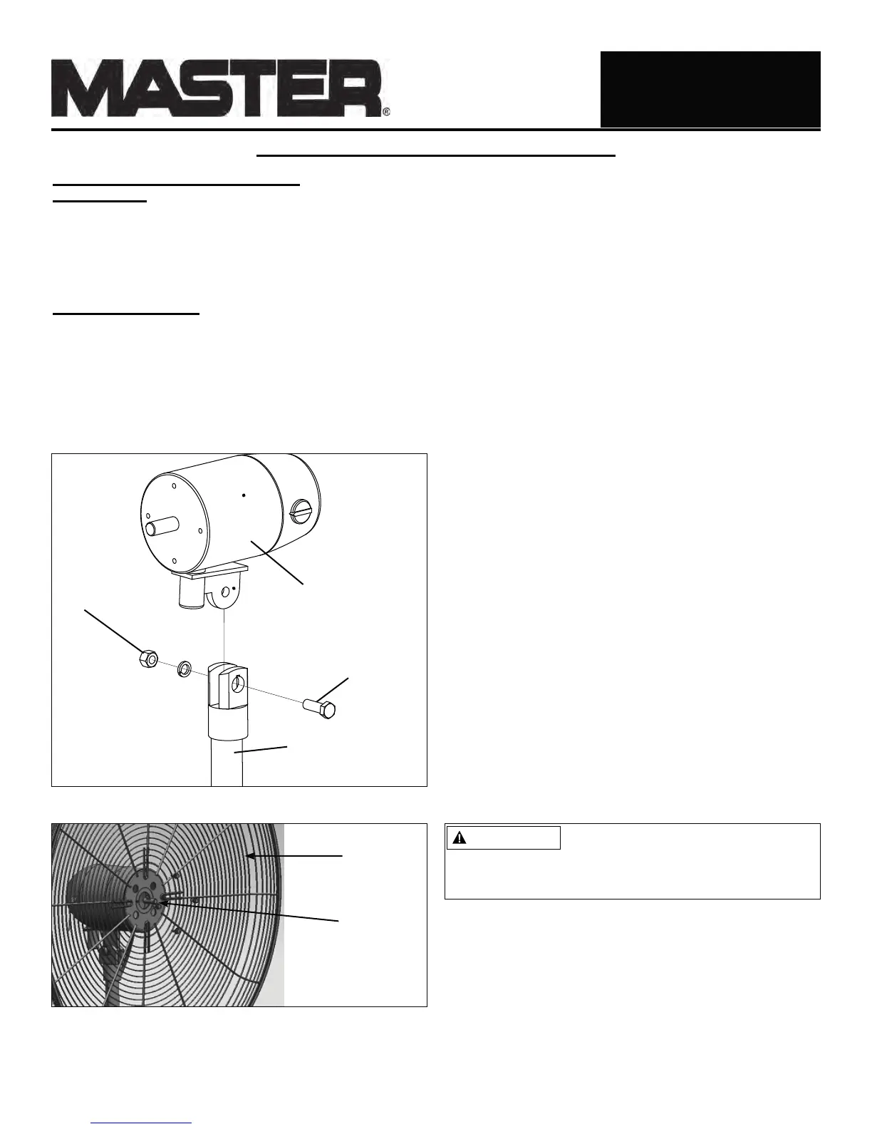
Figure 19: Attaching Rear Guard to Motor
Rear Guard
Motor
Motor Assembly
Pivot Bolt
Nut
Upper Support Pole
Figure 18: Attaching Motor to Motor Support Assembly
Do NOT slide fan blade screw
beyond the groove on the shaft!
This will cause the fan blade to not spin properly
and can cause damage to your fan! Be sure that fan
shaft is flush with front of fan blade assembly.
CAUTION
 Loading...