Page 6 Pinnacle Products International, Inc. Propane Forced Air User’s Manual
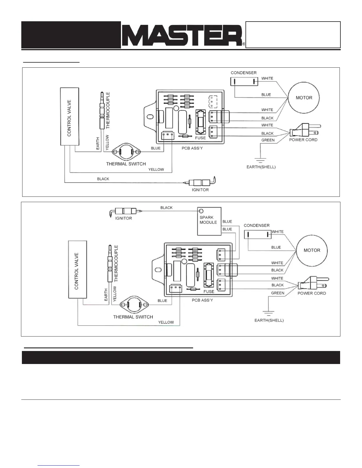
Figure 4. Wiring Diagram for Piezo/Manual Spark Models.
Wiring Diagrams
Figure 5. Wiring Diagram for Continuous Spark Models.
1 Outer Shell 22-524-0075 22-524-0076 22-524-0077 22-524-0077 1
2 Inner Shell Assembly 22-524-0004 22-524-0004 22-524-0005 22-524-0005 1
3 Base 22-501-0003 22-501-0001 22-501-0002 22-501-0002 1
4 Height Controller 22-512-0005 22-512-0005 22-512-0008 22-512-0008 1
5 Base Cover 22-508-0003 22-508-0001 22-508-0002 22-508-0002 1
6 Inner Shell Cap 22-505-0006 22-505-0010 22-505-0011 22-505-0008 1
7 Multi Bracket Assembly 22-504-0002 22-504-0002 22-504-0002 22-504-0003 1
8 Thermal Switch 22-603-0001 22-603-0001 22-603-0001 22-603-0001 1
9 Tubing Assembly 22-605-0001 22-605-0001 22-605-0005 22-605-0005 1
10 Nozzle 22-081-0007 22-081-0014 22-081-0015 22-081-0004 1
Repair Parts List for Propane Construction Heater
NOTE: If any original wiring as supplied with the
heater must be replaced, it must be with type AWG
105°C wire or its equivalent, except as indicated.
NOTE: If any original wiring as supplied with the heater must be replaced, it
must be with type AWG 105°C wire or its equivalent, except as indicated.
Reference Part Number for Models:
Number Description MH-40-GFA MH-60V-GFA MH-125V-GFA MH-150V-GFA Quantity
Propane
Forced Air Heaters
NEVER LEAVE HEATER UNATTENDED
WHILE BURNING, CONNECTED TO A
POWER SOURCE, OR WHILE
CONNECTED TO A FUEL SOURCE