EN
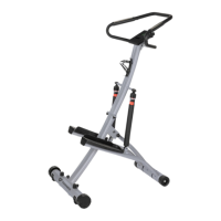
Step 4
C) Connect two sensor wires (27&53) together. See the drawing of (A).
D) Attach upper frame (51) to under frame (1) with Allen bolt (17), flat washer (14), nylon
nut (15) and plastic cap (46).
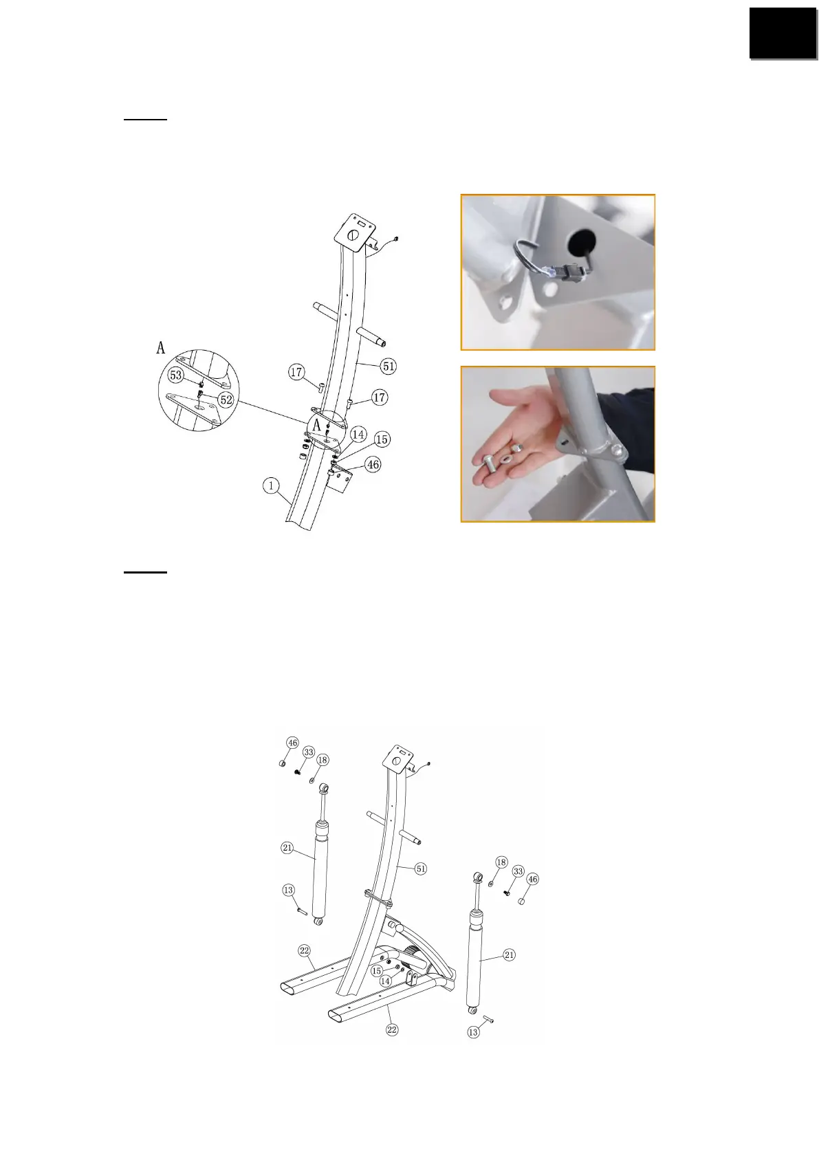
Step 5
B) Attach two hydraulic cylinder (21) to upper frame (51) with hex bolt (33), big flat
washer (18) and plastic cap (46).
B) Attach the other end of hydraulic cylinder (21) to pedal tube (22) with Allen bolt (13), flat
washer (14) and nylon nut (15).
Note: How to adjust the hydraulic cylinder. The cylinder 12 sections, the bigger the
number is, the bigger the resistance is. Turn the top of the cylinder clockwise, the
resistance will become bigger. The number which the arrow point is the exact section.