15
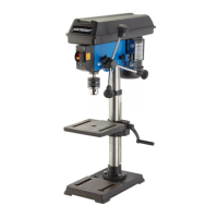
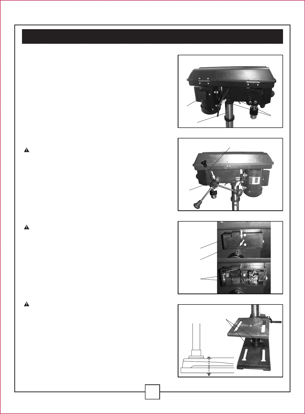
DRILL PRESS HEAD TO COLUMN (Fig. 5)
1. Lift the drill press head assembly (1) carefully and
place the mounting hole of the drill press head onto
the top of the column (2). Make sure the head is
seated properly on the column.
2. Align the direction of the drill press head to the
direction of the base and the table.
3. Tighten the two set screws (3) using an allen wrench.
FEED HANDLES (Fig. 6)
1. Thread the three feed handle rods (1) into the holes
on the feed hub (2).
2. Hand tighten.
Note: One or two of the feed handles may be
removed if an unusually-shaped workpiece interferes
with handle rotation.
LASER BATTERIES (Fig. 7)
1. Turn off the laser.
2. Push the tab (1) located on the laser switch cover
(2) down and towards you, then remove it.
3. Insert 2 “AAA” batteries in the laser battery
compartment (4).
4. Replace the laser switch cover.
CAUTION: Remove the laser light batteries when
the tool is to be stored without use for a few days or
more. If left in position, the batteries might leak and
damage the laser light assembly. Damage due to
leaking batteries is not covered under the warranty.
MOUNT THE DRILL PRESS (Fig. 8)
Your drill press must be securely fastened through the
mounting holes (1) to a stand or work bench with
heavyduty fasteners. This will prevent the drill press
from tipping over, sliding, or walking during operation.
IMPORTANT: If the stand or workbench has a
tendency to move during operation, fasten it securely
to the floor.
V. Assembly and adjustments (continued)
Fig. 5
Fig. 6
Fig. 7
Fig. 8
1
2
2
2
1
3
1
1
3
1
2
 Loading...