12 13
model no. 299-3118-4 | contact us 1-800-689-9928
ASSEMBLY
ASSEMBLY
Assembly
1. Unpack the air compressor. Inspect the unit for damage. If the unit has been damaged, contact the
retailer immediately.
THE CARTON SHOULD CONTAIN:
•
Air compressor.
•
Owner’s manual.
•
Wheel kit(2 shoulder bolts, 2 wheels, 2 flat washers, 2 spring washers, 2 nuts)
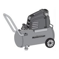
2. Check the air compressor’s identification label to ensure that you have purchased the intended model
and that it has the required pressure rating for its intended use.
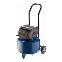
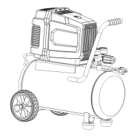
3. Positioning of the air compressor:
a. Position the air compressor near an electrical outlet.
b. The compressor must be at least 12" (31 cm) from any wall or obstruction, in a clean, well-ventilated
area to ensure sufficient air flow and cooling.
c. Place the air compressor on the floor or a hard, level surface. The air compressor must be level to
ensure proper drainage of the moisture in the tank.
5. Connect air hose to compressor.
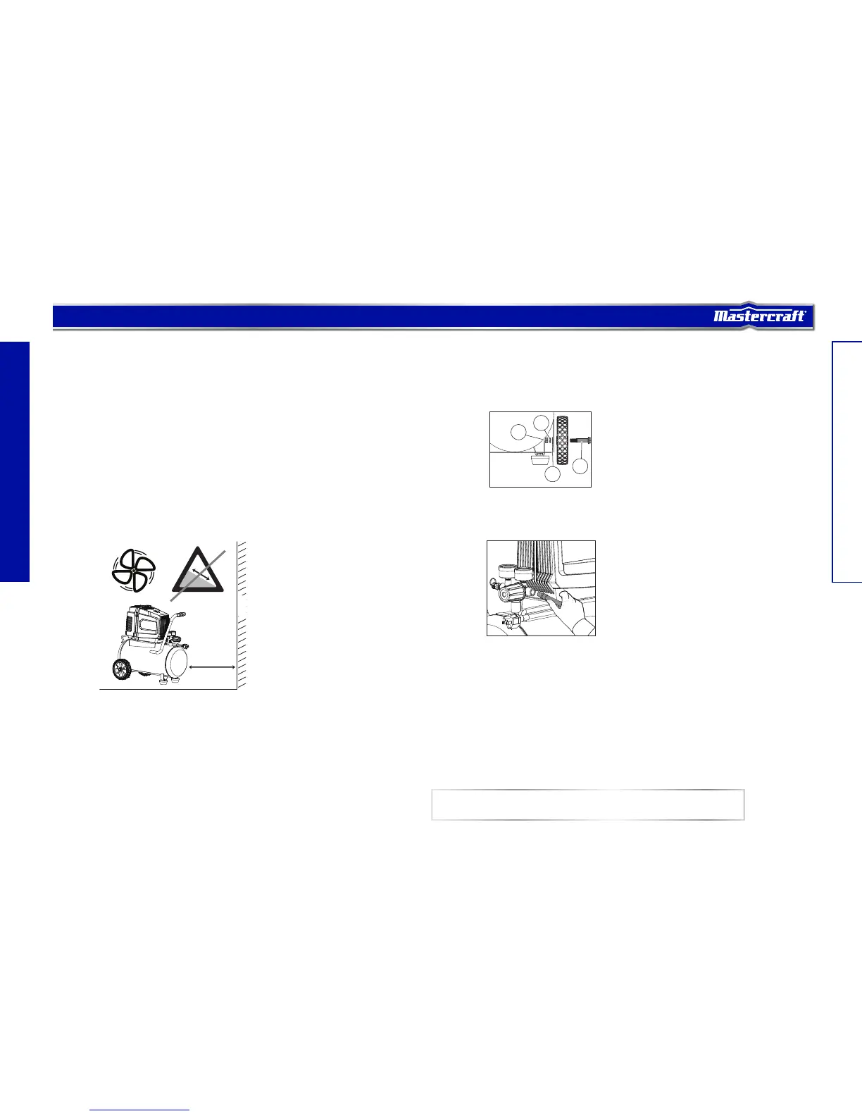
4. Wheel assembly
• Connect air hose (not provided) to the compressor’s air outlet (H).
• Insert the shoulder bolt (1) through one of the wheels.
• Insert shoulder bolt (1) through the bracket on the bottom of the tank assembly. Slide on washer (2), lock
washer (3) and tighten the nut (4).
• Once assembled, roll the air compressor to test the operation of the wheels. Periodically check to ensure
that wheel and axle hardware are secure.
NOTE: ¼" (6.4 mm) NPT air hose is required for connecting to the air compressor.
> 12" /
31 cm
Wall
1
2
3
4
 Loading...