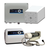
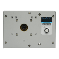
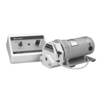
The Masterflex I/P Precision Variable-Speed Modular Drives are designed to control the speed of Masterflex Pump Heads, enabling flow rates from 0.04 to 19 L/min. These 650 rpm drives are capable of mounting up to two Masterflex Pump Heads or other pumps adapted to Masterflex drives.
Function Description
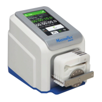
The device operates as a peristaltic pump system, which offers several advantages for fluid handling. Peristaltic pumps are ideal for handling abrasive slurries and corrosive fluids with minimal wear, making them suitable for applications involving substances like titanium dioxide or diatomaceous earth filter aids. Their sealless and valveless design contributes to low maintenance requirements and prevents clogging. The smooth inner surfaces of the tubing facilitate easy cleaning and ensure contamination-free fluid transfer, as the fluid only contacts the tubing material. These pumps are capable of suction lift and priming up to 8.8 meters of water column at sea level. They are also designed for low shearing, which is beneficial for handling shear-sensitive fluids such as latex or fire-fighting foam. Furthermore, Masterflex peristaltic pumps can run dry and pump fluids with high quantities of entrained air, like black liquor soap. Their high volumetric efficiency makes them suitable for metering or dosing applications where high accuracy is crucial. They can handle extremely viscous fluids, and a wide range of tubing and tube materials are available that are suitable for food and pharmaceutical use.
Usage Features
The drive unit should be mounted on a flat horizontal surface, ensuring adequate air flow and an ambient air temperature not exceeding 104°F (40°C). The drives are provided with a grounded plug, but users should be aware that nuisance tripping may occur if used in a GFCI protected circuit. Tubing should be clean and routed with bend radii at a minimum of four times the tube diameter and as short as possible. It is crucial to turn the drive off before removing or installing tubing to prevent fingers or loose clothing from getting caught in the drive mechanism. Users should select a tube size with an appropriate diameter for the required flow rate and viscosity. Information on tubing selection and compatibility, as well as pump head datasheets, can be found on the provided flash drive or on the web. Before cleaning or conducting maintenance, power must be removed from the drive. High voltages exist internally, and extreme caution is advised when servicing internal components.
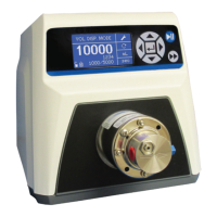
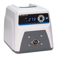
The pump's operation is controlled via a front panel keypad. The POWER (ON/OFF) SWITCH turns the unit on or off. SPEED KEYS allow users to set the pump's speed, with higher numbers corresponding to faster speeds. Depressing a speed key changes the smallest speed units first, followed by an increasing rate of change. The FLOW DIRECTION KEY sets the direction of pump rotation (clockwise/counterclockwise), indicated by an LED annunciator. The motor stops in a controlled manner before reversing direction. The INTERNAL/EXTERNAL KEY changes the drive operation mode between internal (local) control from the front panel keypad (INT) and external (remote) control (EXT). In INT mode, START/STOP, FLOW DIRECTION, and SPEED keys on the front panel determine the operating state. The START/STOP KEY toggles the motor ON/OFF in INT mode but will not start the drive in EXT mode; if pressed in EXT mode, it will stop the drive, requiring a toggle of the EXT Start/Stop to restart. A REMOTE CONNECTOR is available for remote control operation using a DB-9 (or round 18-pin for NEMA 4X) connector. The IEC Power Entry Module/Line Cord connects the line cord to the controller, and a Motor Connector connects the motor to the controller.
For external operation, benchtop models feature inputs controllable by external signals connected to a rear panel 9-pin "D" shell connector, while NEMA 4X models use a bottom 18-pin round connector. These external inputs allow remote equipment or accessories to control the pump. When the INT/EXT key is in the EXT position, starting and stopping the pump is controlled by an external contact closure between specific pins, and pump speed is determined by an externally supplied 0-10V or 4–20 mA source. If front panel speed control is desired with external Start/Stop operation, the INT/EXT key must remain in the EXT position, and a specific jumper (Jumper A) must be in place. The signal common for speed control voltage and current inputs is not referenced to earth ground. The START/STOP, CW/CCW, and Local/Remote inputs are digital, internally pulled up to +5V. Using contact closures is recommended for increased noise immunity. It is important to note that routinely disconnecting and reapplying the AC line to the drive to start and stop the motor can cause drive hardware damage; the drive is designed to use control input signals for this purpose.
Maintenance Features
Tubing should be inspected periodically for tears, cracks, cut marks, abrasions, inability to hold pressure, bubbles in the flow stream, and reduction or loss of flow. Tubing life can be extended by periodically moving worn tubing from the occlusion bed to the suction side of the pump to avoid excessive wear at a specific point.
For fuse replacement, the power switch must be in the off position, and the AC power input line cord disconnected from the receptacle. The fuse can then be removed, checked, and replaced if defective. The fuse type and rating are stated on the rear panel.
Motor brushes should be checked every 6 months or 2,000 operating hours. To replace them, disconnect the AC line cord from the receptacle and the motor cable from the controller. Remove the two vinyl caps covering the brush caps, then carefully unscrew the brush caps on opposite sides of the motor. Withdraw the brushes and examine them for wear. Both brushes should be replaced if either is less than 0.300” (7.6mm) long from base to point. After replacement, screw the brush caps back into the brush holder, replace the vinyl caps, and reconnect the motor and AC line cord.
For cleaning, power must be removed from the pump. The drive enclosure should be cleaned with mild detergents, avoiding immersion or excessive fluid.