Installation Instructions
CAUTION: Failure to read and follow all installation and operating instructions could lead to personal injury and/
or damage to property.
CAUTION: All electrical installations must comply with local building and safety codes and must be performed by
qualied personnel only.
System Overview
• Thiscontrolsystemisintendedtobeusedwithanevaporativecoolerwitha2-speedblowerandawaterpump.Itwillalsooperatea
waterpurgepumporvalve,ifequipped.
• Thecontrolisdesignedforfanmotorsupto1HP(120V)or2HP(240V),withwaterpumpandpurgepumpupto2A(120V)or1A
(240V)
• Thefanmotormaybe120Vor240Vrated.
• Thewaterpumpandpurgepumpmotors/valvessharethesameelectricalsupply,ratedfor120Vor240V.
Included in Kit
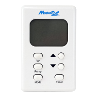
• WallControlThermostat
• 2-SpeedEvaporativeCoolerControl
• WireNutforcommonEarthconnection.
• Spare3.15Ampfuseforcontrol.
• JumperwireforLinktoN-Link(TobeusedonlywhenbothFanandPumpvoltagesarethesame).
Additional Requirements
Dependingonapplicationandinstallation,thefollowingadditionalitemsmayberequired:
• ScrewsorboltsformountingtheApplianceControlBoxandWallControl
• WiringforconnectionbetweenpowersupplyandApplianceControlBox;WallControlandApplianceControlBox;andbetween
ApplianceControlBoxandthecoolerconnectionbox.
• Conduitandwatertightconnectorstoprotectallwiring.
Installation of the Appliance Control Box
CAUTION: To prevent electrical shock and/or damage to the equipment, disconnect electrical power to the system at
the main fuse or circuit breaker before starting the installation, and leave disconnected until the installation is complete.
1) AfterdeterminingasuitableplacetoinstalltheApplianceControlBox,markthelocationofthethreemountingpoints(withthe
‘TOP’indicationuppermost)anddrillpilotholesforthemountingscrews.
2) Determinewhichknockoutlocationswillbeusedforthesystemwiring.
3) Usingasuitabletool,cutouttherequiredknockouts.Makesureyoucutoutthe
correctsizeholeforyourtting.
4) Mounttheboxusingsuitablescrews.
5) Installconduitandconnections,ensuringawatertightseal,especiallyaroundthe
locationswheretheknockoutswereremoved.
6) Runwiring,inaccordancewithlocalandnationalelectricalcodes,tosuitthe
installation.
7) Connectthewiresinaccordancewiththewiringdiagramonnextpage(wiring
diagramalsolocatedontheinsidelidofApplianceControlbox).
WARNING: Use the jumper wire between Link and NLink only
when fan and pump voltages are the same.
Wall Control Thermostat and 2-Speed Evaporative Cooler
Control System • Model 110423-2

