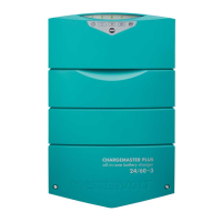
Mass Charger 24/50-2, 24/75, 24/75 (120V), 24/100, 3-24/100, 48/25, 48/50 – User and Installation Manual
4.3.3 DC wiring
Keep the cable connection between charger and batteries
as short as possible. If available, use coloured battery
cables. If this is not possible, mark the plus and the minus
cables with coloured insulating tape (e.g. red for plus and
blue/black for minus). Use the following diameters:
4.3.4 Connection of main batteries
1 Pull the cables through the cable glands of the Mass
Charger.
2 Crimp on ring terminals to the cable:
ring M6 for 24/50-2 and 48/25;
ring M8 for 24/75, 24/75 (120V), 24/100, 48/50
and 3-24/100.
3 Connect the cables to the terminals of the Mass
Charger. Pay attention to the polarity, positive on
positive/negative on negative.
4 Integrate a suitable fuse (charger fuse) in the positive
cable. When using a DC distribution with fuses, no
additional fuse is necessary.
5 Cut the cables to length and crimp on the ring
terminals. Connect the cable to the DC distribution or
batteries.
CAUTION!
Reversing the positive and negative battery
poles will severely damage the Mass Charger.
Lay the positive and negative cables next to each other to
limit the electromagnetic field around the cables. The
negative cable should be connected directly to the
negative post of the battery bank or the ground side of a
current shunt. Do not use the hull or chassis frame as the
negative conductor.
4.4 Battery capacity
Always follow the instructions published by the battery
manufacturer.
Recommended battery capacity
4.5 Battery isolator
If one or more batteries or battery sets must be charged at
the same time via one output, a battery isolator should be
used. This isolates the different battery sets to prevent one
discharging the other. Mastervolt offers several Battery
Isolators. Please refer to www.mastervolt.com .
A battery isolator causes a voltage drop of 0.6V. This can
be compensated in two ways:
By changing DIP switch 4 to On (Diode enabled);
By using the voltage sense function (see section 4.8
on page 9);
CAUTION!
Never use both methods. Your batteries will be
overcharged and severely damaged!
If you use a ‘voltage drop free’ battery isolator, like the
Mastervolt Battery Mate, no compensation is needed.
For a proper installation, see the connection diagram that
comes with the battery isolator.
4.6 Connection of second battery (3A output)
The Mass 24/50-2 MB is standard equipped with a second
charge output which can be used to give a maintenance
charge to a small second battery set like a starter battery.
The maximum charge current of the second output is 3A,
which comes from the main output.
Use 2.5 to 4mm
2
cable for the connection.
Connect the minus of the second battery to the minus
of the main battery.
Connect the plus of the second battery to the +3A
terminal of the Mass Charger (Figure 4 and Figure 5).
Integrate a 10A slow blow fuse in the plus cable.
4.7 Temperature sensor
The standard temperature sensor is provided with 6m
cable and a double-sided tape for easy installation.
1. Make sure that the side of the battery that you want to
place the sensor, is clean and grease-free.
2. Remove the piece of paper from the tape and stick
the sensor on the battery.
3. Plug the modular cable into the terminal at the right of
the Mass Charger (see Figure 4 on page 10). For the
C3 enclosure (refer to specifications) both "RS232"
and "analog" are suitable.
It is not necessary to shorten the cable. When you want to
shorten it anyway please notice the polarity of the plug and
use the old connector as an example.
Now when the battery temperature is low, the charge
voltage increases and when the battery temperature is
high, the charge voltage is decreased. This prevents
overcharge, and gassing, which increases the battery’s life
time substantially.
 Loading...


