EN / MasterBus – Modbus Interface / September 2014 3
3 INSTALLATION
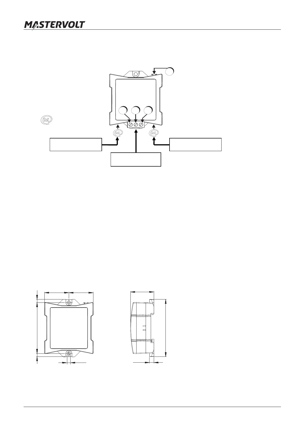
Insert the MasterBus cables first, then connect the Modbus cables to the screw terminal, see figure below.
Overview and functional scheme of the Modbus
4 SPECIFICATIONS
Model: MasterBus - Modbus interface
Article number: 77030800
Delivery also includes: Screw terminal, MasterBus cable, MasterBus Terminating device, User’s manual
Function of instrument: Modbus to MasterBus interface
Languages available: English,Nederlands,Deutsch,Français,Castellano,Italiano,Norsk,Svenska,Suomi,Dansk
Power consumption: 350 mW
MasterBus Powering: No
Din rail mounting: Yes, Din rail 30 mm [1.2 inch]
Protection degree: IP 21
Dimensions: 66 x 78 x 32 mm [2.6 x 3.1 x 1.3 inch]; see drawing below
Weight: Approx. 80 gr [0.18 lb]
1. Modbus B line
2. Modbus A line
3. Modbus Ground
4. MasterBus
communication LED
MasterBus
connector
4
1 2 3
Modbus network
MasterBus network MasterBus network
B A GND
Dimensions in mm [inch]
4,5 [0.18]
69 [2.7]4.0 [0.16]
33 [1.3]
33 [1.3]
6.0 [0.24]
78 [3.1]
32 [1.3]
4.0 [0.16]