6 September 2014 / MasterBus – Modbus Interface / EN
6.5 Entering the values into Modbus
After having written down the values needed, you
have to enter these into your Modbus system. The
next example shows how to enter the values and
how to communicate with the chosen variable
“Override” of MasterBus device “INT DC Relay”.
6.5.1 Modbus function code 23
The Modbus to MasterBus interface uses the
Modbus function 23 communication protocol.
See the Modbus Application Protocol Specification
V1.1b at www.modbus.org for more details.
The dataframe tables below describe the variables
used in Modbus function 23 (0x17) Read/Write
Multiple Registers Protocol.
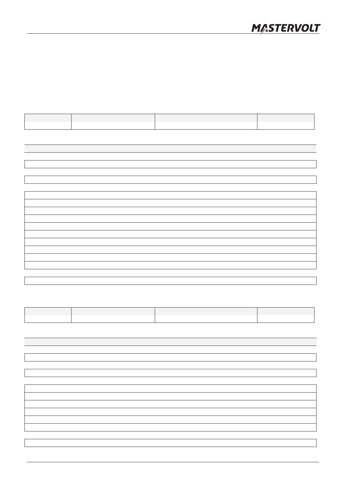
Request data frame
Address field Function code (Function 23) Data (Read Starting Address, etc. ) CRC (Error check)
1 Byte 1 Byte 21 Bytes 2 Bytes
Request
Variable Size Value
Bus address 1 Byte Variable
Function code 1 Byte 0x17 (Fixed)
Read Starting Address 2 Bytes 0 (Fixed)
Quantity to Read 2 Bytes 6 (Fixed)
Write Starting Address 2 Bytes 0 = read / 1 = write
Quantity to Write 2 Bytes 6 (Fixed)
Write Byte Count 1 Byte 12 (Fixed)
IDAL 5 bit value 1 Byte Variable
IDB 3 Bytes Variable
TabNr 2 Bytes Variable
Index 2 Bytes Variable
Value 4 Bytes Variable
CRC 2 Bytes Calculated
Response data frame
Address field Function code (Function 23) Data (Read Starting Address, etc. ) CRC (Error check)
1 Byte 1 Byte 13 Bytes 2 Bytes
Response
Variable Size Value
Bus address 1 Byte Variable
Function code 1 Byte 0x17 (Fixed)
Byte Count 1 Byte 0x0C (Fixed)
IDAL 5 bit value 1 Byte Variable
IDB 3 Bytes Variable
TabNr 2 Bytes Variable
Index 2 Bytes Variable
Value 4 Bytes Variable
CRC 2 Bytes Calculated