Figure
3.1
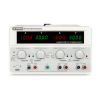
①CH1 current display window,
②CH1 voltage display window
③CH2 current display window
④CH2 voltage display window
⑤CH1 output switch
⑥CH2 current adjustment knob
⑦CH2 voltage adjustment knob
⑧CH3 overload indicator
⑨CH3 output terminal
⑩CH2 constant pressure indicator
⑪CH2 constant current indicator
⑫CH2 output terminal
⑬CH2 output switch
⑭Ground terminal
⑮CH1 voltage adjustment knob
⑯CH1 output terminal
⑰Instrument power switch
⑱CH1 current adjustment knob
⑲One-key series/parallel/function button
⑳Series and parallel indicator lights
○21CH1 constant current indicator
○22CH1 constant pressure indicator
The rear panel of MPS-H-3 series DC power supply is shown in the figure below.
 Loading...