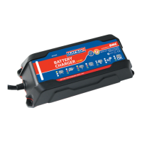
The device is a Multi-Use Smart Battery Charger, available in three models: AE150E, AE300E, and AE500E. These models are designed to charge and maintain 12-volt Lead Acid, AGM, and Gel-Cell batteries. The charger is not intended for use with other battery types such as Dry Cell, Nickel Cadmium, or Nickel Metal Hydride, as this could lead to bursting, damage, or injury.
Function Description:
The Matson Multi-Use Smart Battery Charger is designed to safely and efficiently charge and maintain 12V batteries. It features intelligent charging modes and LED indicators to communicate the charging status, including "No AC Power," "Stand By," "Charging," "Defective Battery," "75% Charged," and "Fully Charged." The charger automatically shifts to maintenance mode once the battery is fully charged, ensuring optimal battery health and preventing overcharging. It is powered by DHC and is designed for ease of use and safety, with various precautions outlined in the manual to prevent accidents like battery explosions or electric shock.
Important Technical Specifications:
- Input Voltage: 220-240Vac 1A 50/60Hz
- Output Current (Max.):
- AE150E: 1.5A
- AE300E: 3A
- AE500E: 5A
- Charge Voltage (Max.): 14.8V
- Weight: 1.1 lbs
- Size (L x W x H): 170 x 73 x 48mm / 6.7" x 2.9" x 1.9"
- Operating Temperature Range: 0°C (32°F) to 50°C (122°F)
- Battery Compatibility: 12-volt Lead Acid, AGM, and Gel-Cell batteries only.
Usage Features:
The charger comes with two cable assembly options: Battery Clip Cable Assembly and Ring Terminal Cable Assembly, providing flexibility for different connection needs. It also includes LED indicators for clear status communication and mounting holes for secure installation.
Setting Up & Operations:
- Ventilation: Ensure the charging area is well-ventilated.
- Mounting: Mount the charger away from vehicle repair or service areas. Avoid starting or running an engine near batteries being charged.
- Power Capacity: Verify that the total amperage used by the charger does not exceed the supply source's capacity. Consult a qualified electrician if unsure.
- Connecting/Disconnecting: Connect and disconnect DC output clips only after setting any charger switches to the "off" position and removing the AC cord from the electrical outlet. Never allow clips to touch each other.
- Battery Terminals: Clean battery terminals if necessary. Clamp the black clip (NEG, -) to the negative battery terminal and the red clip (POS, +) to the positive battery terminal.
- AC Connection: Connect the charger to a grounded power receptacle wired in compliance with local electrical codes.
- Side-Mounted Batteries: For side-mounted batteries, use a lead post adapter. Plain bolts are not safe and will not allow for accurate readings.
DC Connection Precautions:
- Always connect and disconnect DC output clips only after removing the AC cord from the electrical outlet.
- Never allow clips to touch each other.
- If the charger has an output voltage selector switch, refer to the car owner's manual to determine the battery voltage and set the charger to the correct voltage. If no selector switch is provided, ensure the battery voltage matches the charger's output voltage rating.
Charging When Battery is Installed in Vehicle:
To reduce the risk of sparks and battery explosion:
- Cable Positioning: Position AC and DC cables to minimize damage from the hood, door, or hot engine parts. If closing the hood during charging, ensure it doesn't touch metal parts of the battery clips or cut cable insulation.
- Clearance: Stay clear of fan blades, belts, pulleys, and other moving parts.
- Grounding: Determine if the battery post is grounded to the chassis.
- Negative-Grounded Vehicle: Connect the POSITIVE (red) clip to the POSITIVE (POS, +) ungrounded battery post. Connect the NEGATIVE (black) clip to the vehicle chassis or engine block away from the battery (not sheet-metal body parts). Connect to a heavy gauge metal part of the frame or engine block.
- Positive-Grounded Vehicle: Connect the NEGATIVE (black) clip to the NEGATIVE (NEG, -) ungrounded battery post. Connect the POSITIVE (red) clip to the vehicle chassis or engine block away from the battery (not carburetor, fuel lines, or sheet-metal body parts). Connect to a heavy gauge metal part of the frame or engine block.
- Polarity Check: POSITIVE (+) battery posts usually have a larger diameter than NEGATIVE (-) posts.
- Disconnection: When disconnecting, first disconnect the AC cord, then remove the clip from the vehicle chassis, and finally remove the clip from the battery terminal.
Charging When Battery is Outside Vehicle:
To reduce the risk of sparks and battery explosion:
- Polarity Check: Check battery post polarity. POSITIVE (+) posts are usually larger than NEGATIVE (-) posts.
- Cable Attachment: Attach at least a 60 CM-long 6-gauge (AWG) insulated battery cable to the NEGATIVE (NEG, -) battery post.
- Final Connection: Do not face the battery when making the final connection. Position yourself and the free end of the cable as far away from the battery as possible, then connect the NEGATIVE (black) charger clip to the free end of the cable.
- Connections:
- Connect the POSITIVE (red) charger clip to the POSITIVE (POS, +) post of the battery.
- Connect the NEGATIVE (black) charger clip to the NEGATIVE (NEG, -) post of the battery.
- Connect the AC supply cord to the electrical outlet.
- Disconnection: When disconnecting, always reverse the connection procedure, breaking the first connection as far away from the battery as practical.
- Marine Batteries: Marine batteries must be removed and charged on shore unless the equipment is specifically designed for marine use.
AC Connections:
- Voltage Check: This charger is for 220-240 Vac. Verify your AC voltage matches the charger's requirements.
- Grounding: The plug must be connected to a properly installed and grounded outlet in accordance with local codes.
- Plug Fit: The plug pins must fit the receptacles. Do not use with an ungrounded system.
- No Alterations: Never alter the AC cord or plug. If it doesn't fit the outlet, have a qualified electrician install a properly grounded outlet. Improper connection can lead to electric shock.
Charging Indication (AE150E):
- NO AC Power (all lights off): No AC power applied. Check the AC end.
- STAND BY (green blinking only): Clamps not connected to battery properly.
- CHARGING (both lights on): Charger is charging the battery.
- DEFECTIVE BATTERY (red lit only): Battery cannot hold a charge. Immediate replacement recommended.
- 75% CHARGED (green lit & red blinking): Battery is 75% charged and ready for load test or service.
- FULLY CHARGED (green lit only): Battery is fully charged. Charger shifts to maintenance mode.
Charging Indication (AE300E & AE500E):
- NO AC Power (all lights off): No AC power applied. Check the AC end.
- STAND BY (green blinking only): Clamps not connected to battery properly.
- CHARGING (green & red lit): Charger is charging the battery.
- DEEPLY DISCHARGED BATTERY (yellow blinking, green & red lit): Takes more time to charge. Indication changes to "yellow (defective battery)" after 36 hours of charging.
- DEFECTIVE BATTERY (yellow lit only): Battery cannot hold a charge. Immediate replacement recommended.
- 75% CHARGED (green lit & red light blinking): Battery is 75% charged and ready for load test or service.
- FULLY CHARGED (green lit only): Battery is fully charged. Charger shifts to maintenance mode.
Maintenance Features:
The manual emphasizes several maintenance and safety practices:
- Cleaning: Disconnect all batteries and unplug the charger from the wall outlet before cleaning. Use a slightly dampened cloth to clean the housing and lead sets; do not use solvents or soaps.
- Cord Care: Place power cords where they will not be stepped on, tripped over, or subjected to stress or abuse.
- Damage Inspection: Do not operate the charger with a damaged cord or plug. Replace immediately. Do not operate if it has received a sharp blow, been dropped, or otherwise damaged. Take it to an authorized service center for repair.
- Disassembly: Do not disassemble the charger. Take it to an authorized service center for repair when needed. Incorrect reassembly can lead to electric shock or fire.
- Battery Inspection: Inspect the battery for cracked or broken cases or covers. Do not use the charger if the battery is damaged.
- Water Levels (for non-sealed batteries): If the battery is not sealed maintenance-free, add distilled water to each cell until the battery acid reaches the specified level. Do not overfill.
- Frozen Batteries: Never attempt to charge a frozen battery. Allow it to return to room temperature before connecting.
- Exposure: Do not expose the charger to direct sunlight, rain, or snow. It is not suggested to expose the charger to moisture or inclement weather.
- Battery Acid Contact: In case of contact with battery acid, wash skin or clothing immediately with soap and water. If acid enters the eye, flood with running cold water for at least 10 minutes and seek immediate medical attention.
- Explosive Gases: Always ensure good ventilation when charging. Avoid smoking, striking matches, or causing sparks near the battery. Wear complete eye protection and protective clothing. Have fresh water and soap nearby.
- Metal Objects: Remove personal metal items (rings, bracelets, necklaces, watches) when working with a lead-acid battery to prevent short circuits and severe burns.
Troubleshooting (AE150E, AE300E, AE500E):
- No LED lit:
- Possible Cause: AC end is not making a good connection.
- Solution: Check for poor connection at the AC side.
- Green LED keeps blinking (AE150E) / Green LED keeps blinking (AE300E/AE500E):
- Possible Cause: Clamps are not making a good connection.
- Solution: Check for poor connection at the battery and frame.
- Red LED illuminated right away when connecting onto a battery (AE150E) / Yellow LED illuminated right away when connecting onto a battery (AE300E/AE500E):
- Possible Cause:
- Incorrect battery voltage.
- Battery is at full charge capacity.
- Solution:
- Verify the charger selector switch is in the correct 12V position to match the battery's voltage. The charger will warn if connected to an incorrect application.
- If the battery is full, it will continue in maintenance/float mode until voltage drops, then resume maintenance charging.
If troubleshooting does not resolve the issue, contact the distributor for information. For support, inquiries can be sent to sales@tridon.com.au.