EasyManua.ls Logo

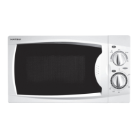
Matsui M130TCS User Manual

Matsui M130TCS
36 pages
To Next Page IconTo Next Page
Page #1 background imageLoading...
Page #1 background image
P/NO : 3828W5S1799 April, 2001
Printed in Korea
MICROWAVE OVEN
SERVICE MANUAL
MODEL: M130TCS
CAUTION
BEFORE SERVICING THE UNIT, READ THE SAFETY PRECAUTIONS IN THIS MANUAL.

Questions and Answers:

Matsui M130TCS Specifications

General IconGeneral
Control TypeTouch
Cooking Levels5
Turntable Diameter255 mm
Weight10.5 kg
ColourWhite

Summary

MICROWAVE OVEN SERVICE MANUAL

CAUTION BEFORE SERVICING

Important safety warning before servicing the unit.

SAFETY PRECAUTIONS

MICROWAVE RADIATION WARNING

Warning about potential exposure to microwave energy during operation or servicing.

SPECIFICATIONS

MODEL M130TCS DETAILS

Technical specifications for the Matsui M130TCS microwave oven.

CAUTIONS

HIGH VOLTAGE AND REPAIR SAFETY

Critical safety warnings and precautions for servicing high-voltage microwave ovens.

INSTALLATIONS

EARTHING INSTRUCTIONS

Guidelines for proper grounding of the microwave oven for safety.

OPERATING INSTRUCTIONS

CONTROL PANEL OVERVIEW

Description of the microwave oven's control panel features and buttons.

OPERATING SEQUENCE

SETTING THE CLOCK AND COOKING

Step-by-step guide for setting the clock and basic microwave cooking operations.

SCHEMATIC DIAGRAM

POWER AND CONTROL CIRCUIT BOARD

Electrical schematic illustrating the power and control circuits of the microwave.

CIRCUIT DESCRIPTION

GENERAL CIRCUIT DETAILS

Explanation of the microwave oven's internal circuit functions and operation.

SERVICE INFORMATION

TOOLS AND MEASURING INSTRUMENTS

List of necessary tools and instruments for microwave oven servicing.

MICROWAVE LEAKAGE TEST

Procedure and precautions for testing microwave radiation leakage.

MEASUREMENT PROCEDURES

MEASUREMENT WITH OUTER CASE REMOVED

Guidelines for measuring microwave leakage after component replacement.

MEASUREMENT WITH FULLY ASSEMBLED OVEN

Procedure for measuring microwave leakage on a completely assembled oven.

MEASUREMENT OF MICROWAVE POWER OUTPUT

DISASSEMBLY AND ADJUSTMENT

Instructions for disassembling the microwave oven and adjusting components.

DISASSEMBLY AND ADJUSTMENT (Continued)

DOOR AND HIGH VOLTAGE COMPONENTS REMOVAL

Steps for removing door, high voltage transformer, fan motor, capacitor, and diode.

DISASSEMBLY AND ADJUSTMENT (Continued)

AIR DUCT AND MAGNETRON REMOVAL

Procedures for removing the air duct assembly and magnetron.

DISASSEMBLY AND ADJUSTMENT (Continued)

PCB ASSEMBLY AND INTERLOCK SYSTEM

Steps for removing PCB assembly and details on the interlock mechanism.

INTERLOCK CONTINUITY TEST

SWITCH CONTINUITY TESTING

Procedure to test the continuity of primary, monitor, and secondary interlock switches.

COMPONENT TEST PROCEDURE

HIGH VOLTAGE TRANSFORMER AND MAGNETRON TESTS

Resistance testing procedures for the high voltage transformer and magnetron.

COMPONENT TEST PROCEDURE (Continued)

HIGH VOLTAGE CAPACITOR AND DIODE TESTS

Testing procedures for the high voltage capacitor and diode using an ohmmeter.

COMPONENT TEST PROCEDURE (Continued)

RELAY, FAN MOTOR, AND TURNTABLE MOTOR TESTS

Procedures for testing relay continuity and motor resistance.

TROUBLE SHOOTING

COMMON TROUBLESHOOTING CONDITIONS

Common issues like oven not working, low power, and sparks, with causes and remedies.

TROUBLE SHOOTING (Continued)

CONTROL CIRCUIT AND DISPLAY ISSUES

Troubleshooting defective control circuits and display problems.

TROUBLE SHOOTING (Continued)

OVEN NOT OPERATING AND FUSE ISSUES

Diagnosing problems where the oven does not operate or the fuse blows.

TROUBLE SHOOTING (Continued)

START BUTTON AND HEATING ISSUES

Troubleshooting issues with the start button, fan motor, oven lamp, and low heat production.

TROUBLE SHOOTING (Continued)

NO MICROWAVE OSCILLATION

Diagnosing and resolving issues with no microwave oscillation when other functions work.

TROUBLE SHOOTING (Continued)

INCORRECT POWER LEVEL OUTPUT

Troubleshooting incorrect power output when setting lower power levels.

EXPLODED VIEW INTRODUCTION

DOOR PARTS

CONTROL PANEL PARTS

OVEN CAVITY PARTS

LATCH BOARD PARTS

INTERIOR PARTS

BASE PLATE PARTS

SCHEMATIC DIAGRAM OF P.C.B

MAIN PCB CIRCUIT LAYOUT

Detailed schematic diagram of the printed circuit board (PCB) layout.

PRINTED CIRCUIT BOARD

PCB COMPONENT IDENTIFICATION

Visual representation and labeling of components on the printed circuit board.

Related product manuals