10 0 W R M S /8 OHM PER CHAN NE L
PEAK OUTPUTVOLTAGE:28 VOLTS
WARNING
*.FOR CONTINUEDPROTECTION AGAINS T
RISK OF FIRE REPLACEONLY W ITH SAME
TYPE A ND RATING OFFUSE
*. T H E U N IT IS F O R IN D O O R U S E O N LY
*.THEUNITMUSTBEEARTHED
*.FOR PROFESSIONALUSE ONLY
F us e :3 .5 A
AC:230V
HIGH
100 W R M S /8 OHM PER CHANNEL
PEAK OUTPUT VOLTAGE:28 VOLTS
WARNING
*.FOR CONTINUED PROTECTION AGAINST
RISK OFFIRE REPLACE ONLY W ITH SAM E
TYPE AND RATING OFFUSE
*.THE UN IT IS FOR IN DOOR USE ON LY
*.THEUNITMUSTBEEARTHED
*.FOR PROFESSIONALUSE ONLY
F us e :3 .5 A
AC:230V
MAX 7136
3
2
1
4
MAX 7136
Professional PA amplifier
CONTROLS
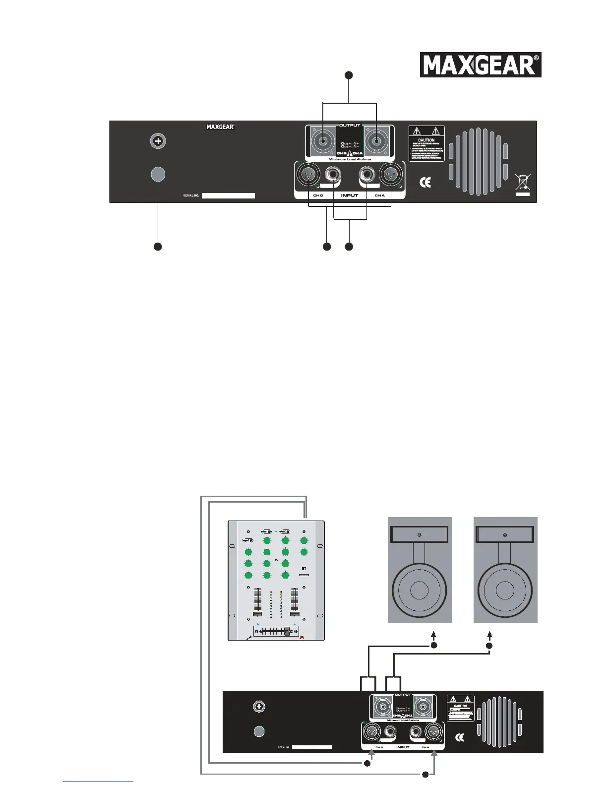
1. Inputs
XLR connectors.
The inputs of the amplifiers two channels receive high impedance line signals from equipment wi th high
level outputs.
2. Link
JACK connectors.
These connectors are connected in parallel with the respective XLR connectors. This enables a second unit
(e.g. another amplifier) to be daisy-chained to the first. It is thus possible to power several amplifiers
using the same signal, forming more powerful sound reinforcement systems.
3. Outputs
Speakon connectors (minimum impedance 4 Q).
NOTE: to avoid possible damage to the loudspeaker enclosures, only connect enclosures or speaker sys-
tems compatible with the power load and impedance limits indicated for the amplifier (regarding this, con-
sult the technical specifications chapter for reference to your specific amplifier model). Use only loudspea-
ker enclosure cables, never signal cables, i.e. those normally used for microphones, instruments and
audio equipment in general.
4. A.C.
Power Input.
HOOK UP DIAGRAM