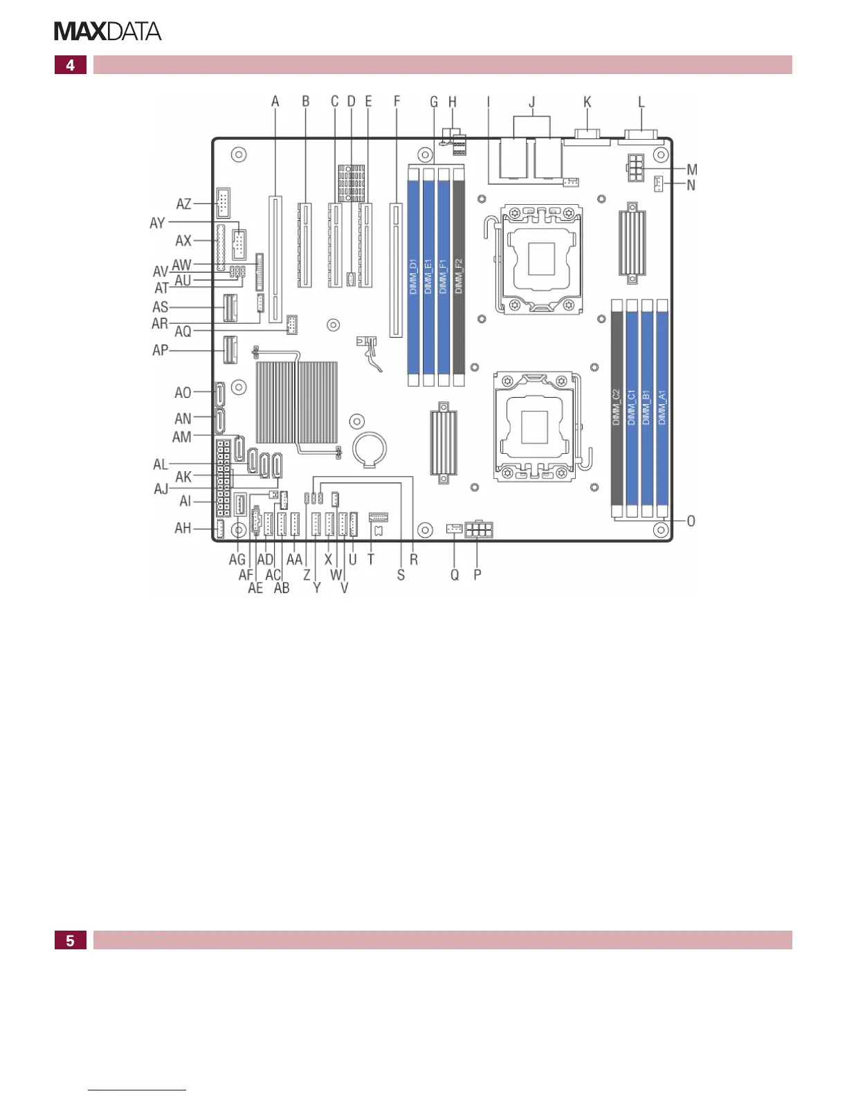
Server Board Connector and Component Locations
2 MAXDATA PLATINUM 500 I M8 – Quick Start Guide
A. Slot2,PCI32bit/33MHz S. Jumper (not in use) AK. SATA port 3
B. Slot3,PCIeGenIIx4 T. TPMheader AL. SATA port 4
C. Slot4,PCIeGenIIIx8 U. LCPheader AM. SATA port 5
D. RMM 4 LITE V. System fan 6 header AN. SATA port 0
E. Slot5,PCIeGenIIIx8,open-ended W. HSBPI2Cheader AO. SATA port 1
F. Slot6,PCIeGenIIIx16 X. System fan 5 header A P. SCU 1
G. DIMMsocketsofCPU2(channelsD,E,F) Y. System fan 4 header AQ. eUSB SSD header
H. Diagnostic LEDs Z. ME update jumper AR. RAID upgrade key
I. CPU2fanheader AA. System fan 3 header AS. SCU 0
J. USB and network connectors AB. System fan 2 header AT. Passwordclearjumper
K. Video port AC. SATASGPIO AU. BIOS recovery jumper
L. Serial port A AD. System fan 1 header AV. BMC update jumper
M. CPU2power AE. PMBusheader AW. RMM 4 header
N. System fan 7 header A F. HDD LED header AX. Front panel header
O. DIMMsocketsofCPU1(channelsA,B,C) AG. Type A USB port AY. USB header
P. CPU1power AH. IPMBheader AZ. Serial port B header
Q. CPU1fanheader AI. Main power
R. BIOS default jumper AJ. SATA port 2
Hard Disk Drive Numbering
The HDDs of each 4x backplane are numbered from bottom to top in ascending order.
If two backplanes are in use and both are connected to the same controller, the lower four drive
bays are connected to ports 0 to 3, while the upper four drive bays are connected to ports 4 to 7.
Perdefault,theHDDsnumbersandpositionsareasfollows:
The HDDs of each 8x backplane are numbered from top to bottom in ascending order.
3.5" hot-swap HDDs 2.5" hot-swap HDDs
CMOS
battery
CPU 2
CPU 1