40 41
EN
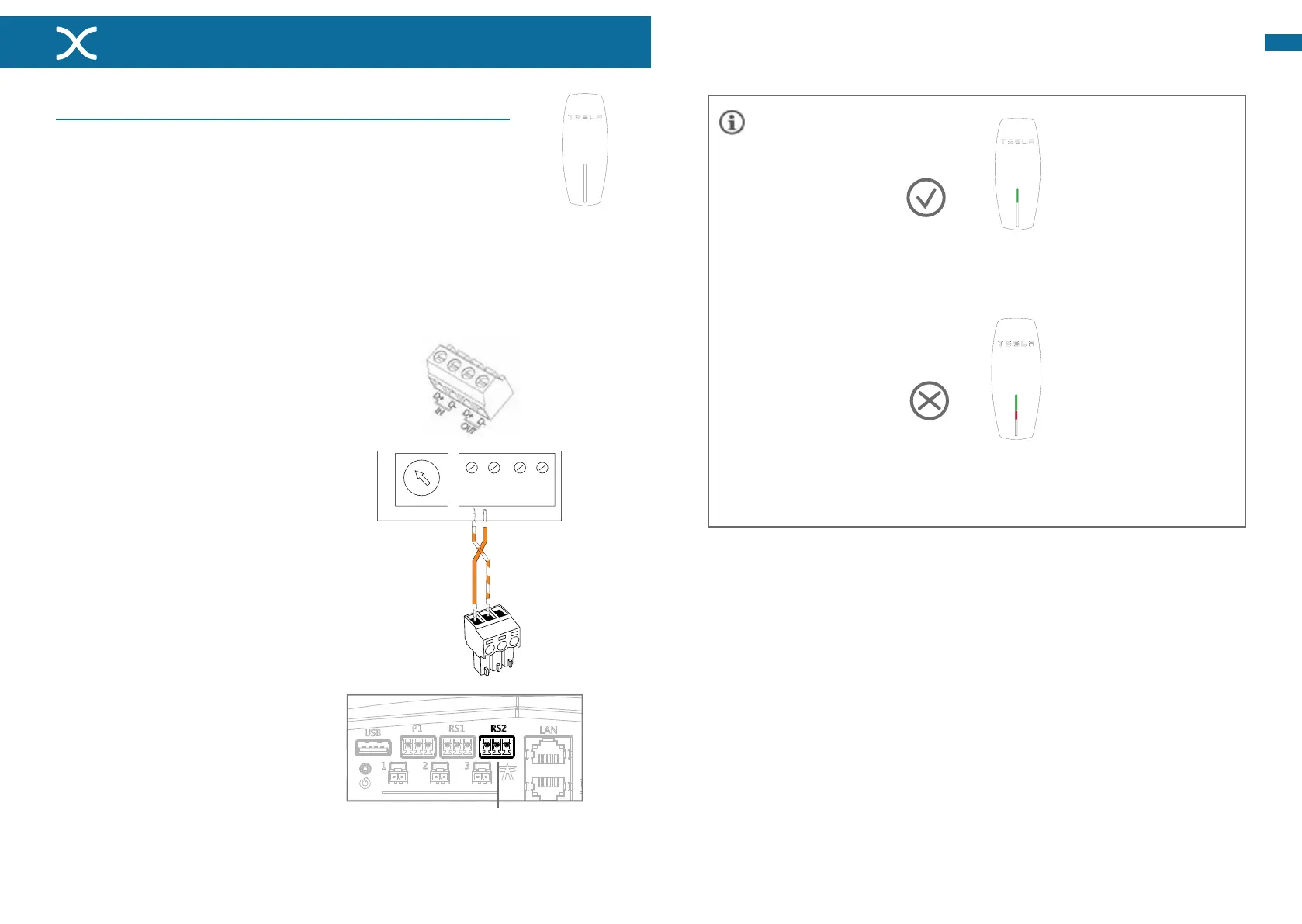
04 - Connecting the charging station
Option4.1-Connecting a Tesla Wall Connector
Install a circuit breaker and/or earth leakage circuit breaker for each
chargingstationatthemaximalpoweravailable.Seep.33.
Follow the installation instructions of the charging station. These
instructions can be found in the installation manual of the charging
station.
A.
B.
Set the Wall Connector to Slave mode
by placing the rotary switch in F
position.
On the Maxem side connect the
supplied green Phoenix connector
to the data cable. 2 wires need to be
connected:
• Connect wire 1 (orange-white) to
port2.
• Connectwire2(orange)toport1.
Connect the green Phoenix connector
toportRS2ofMaxem.
Connect the data cable to the IN port of
theclampblockoftheWallConnector:
• Connect wire 1 (orange-white) to
D+
• Connectwire2(oranje)toD-
Place a suitable UTP (CAT5 or CAT6) of the Wall Connector to Maxem. (To prevent
electromagneticinterferenceattheRS485connection,itisrecommendedtouseFTP
CAT6cableatdistancemorethan25m.Max:50m).
C.
F.
G.
E.
D.
F
D+ D- D+ D-
In Uit
RS2 poort voor
laadstation
REVISION
TITLE:
A4
DWG NO.
SCALE:1:2 SHEET 1 OF 2
WEIGHT:
A A
B B
C C
D D
E E
F F
4
4
3
3
2
2
1
DATESIGNATURE
DO NOT SCALE DRAWING
MATERIAL:
NAME
1
DRAWN
LINEAR:
CHK'D
APPV'D
MFG
Q.A
ANGULAR:
FINISH:
TOLERANCES:
EDGES
UNLESS OTHERWISE SPECIFIED:
DIMENSIONS ARE IN MILLIMETERS
SURFACE FINISH:
DEBURR AND
BREAK SHARP
Maxem5-R4
1
2
3
TopLEDisgreen;theWallConnectorisreadytocharge.
Correct LED
indication
See installation manual Tesla Wall Connector for more information.
Top LED is green, center LED blinks red 4x; the Wall
Connector is set to Slave, but is not communicating
withMaxem..
Incorrect LED
indication
 Loading...