42 43
EN
REVISION
TITLE:
A4
DWG NO.
SCALE:1:2 SHEET 1 OF 2
WEIGHT:
A A
B B
C C
D D
E E
F F
4
4
3
3
2
2
1
DATESIGNATURE
DO NOT SCALE DRAWING
MATERIAL:
NAME
1
DRAWN
LINEAR:
CHK'D
APPV'D
MFG
Q.A
ANGULAR:
FINISH:
TOLERANCES:
EDGES
UNLESS OTHERWISE SPECIFIED:
DIMENSIONS ARE IN MILLIMETERS
SURFACE FINISH:
DEBURR AND
BREAK SHARP
Maxem5-R4
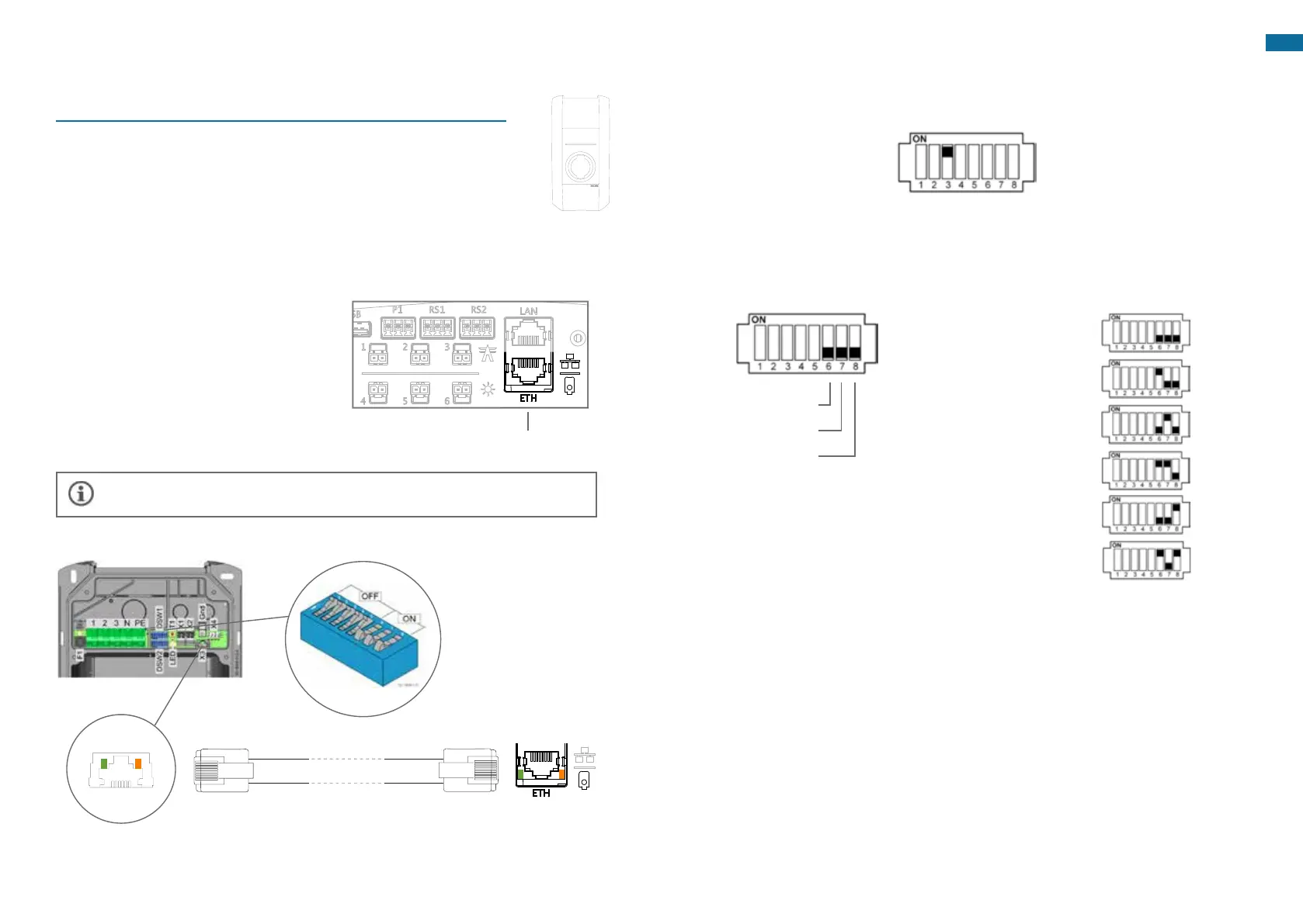
Option4.2-Connecting a KEBA charging station
Install a circuit breaker and/or earth leakage circuit breaker at the
maximalpoweravailable. Seep.33.
Follow the installation instructions of the charging station. These
instructions can be found in the installation manual of the charging
station.
Place a suitable UTP (CAT5 or CAT6) cable from the charging station to Maxem and
clenchRJ45connectorsonbothsides.
Connect the UTP cable to the Ethernet
port of the charging station and the
ETHportofMaxem.
It is advisable to test the network cable with the help of a cable tester.
DSW1 - Power (paragraph above)
DSW2 - Addressing (paragraph below)
Data activity on ETH port
Maxem
Data activity on ETH port
Keba P20 or P30
UTP cable with RJ45 connectors
A.
B.
C.
D.
ETH port for
charging station
REVISION
TITLE:
A4
DWG NO.
SCALE:1:2 SHEET 1 OF 2
WEIGHT:
A A
B B
C C
D D
E E
F F
4
4
3
3
2
2
1
DATESIGNATURE
DO NOT SCALE DRAWING
MATERIAL:
NAME
1
DRAWN
LINEAR:
CHK'D
APPV'D
MFG
Q.A
ANGULAR:
FINISH:
TOLERANCES:
EDGES
UNLESS OTHERWISE SPECIFIED:
DIMENSIONS ARE IN MILLIMETERS
SURFACE FINISH:
DEBURR AND
BREAK SHARP
Maxem5-R4
PutDSW1.3ONtoactivatesmartcharging.
SettheDIPswitchesofDSW1onthemaximalavailablepower.Andleavetherestofthe
DIPswitchesonOFF.
E.
F.
Example 10A
DSW1.6OFF
DSW1.7OFF
DSW1.8OFF
10A
13A
16A
Maximal current strength
20A
25A
32A
Settings on DSW1
1 of 3-phase
See installation manual KEBA P20/P30 for more information
SwitchotheKebaP20/P30(theDIPswitchsettingsonlybecomeactiveafterareset
ofthechargingstation).
G.
 Loading...