Technical Description
Air Amplifiers Revision 11.2011
11
Control air is supplied externally for air amplifiers with a port X. It is branched off
from the drive compressed air (upstream of pressure reduction), being charged
through pipes to port X. A directional control valve in the control pipe can be used to
switch the air amplifier on or off.
Example:
Drive compartment II = 4 bars
+ compression
compartment I
= 4 bars
Compression
compartment II
= 8 bars
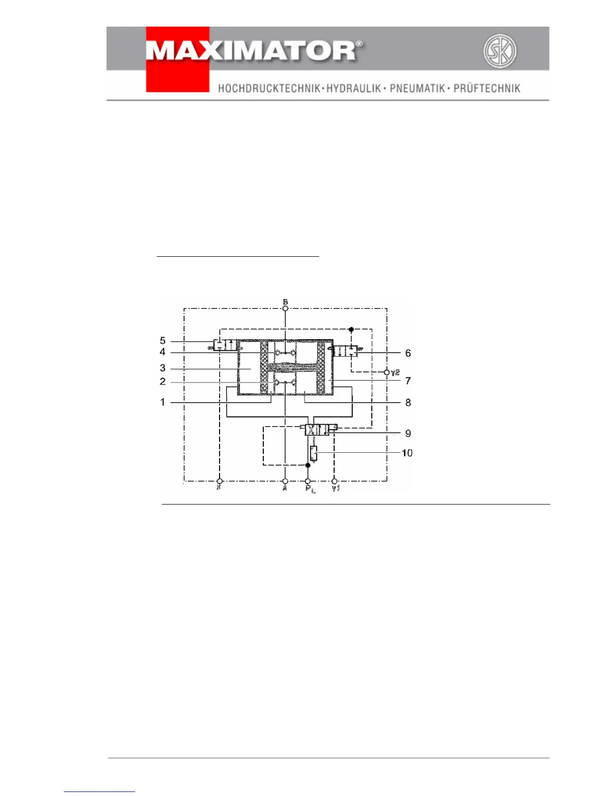
Fig. 4: How MPLV 2, SPLV 2 and GPLV 2 work
1 Compression compartment II
2 Non-return valves inlet
3 Drive compartment II
4 Non-return valves outlet
5 Pilot valve
6 Pilot valve
7 Drive compartment I
8 Compression compartment I
9 Control slide valve
10 Exhaust
P
L
= Drive pressure
B = Pressure outlet
Y
2
= Exhaust air from pilot valve
A = Charge pressure
Y
1
= Exhaust air from control valve
X = Control pipe
(possible external port
for control pipe)