INSTALLATION
MERLIN
WI-FI
MAESTRO
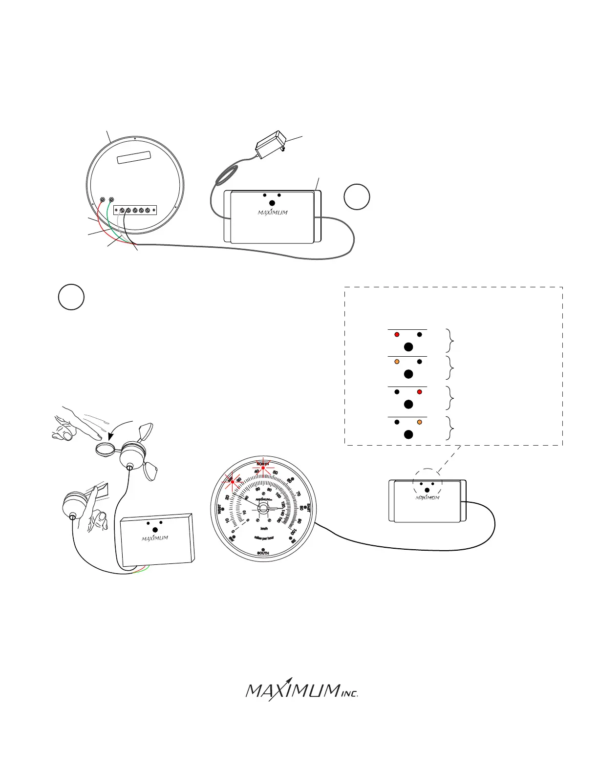
AC ADAPTER
1 2 3 4
IN
COM
OUT
5
BENCH TEST (CONTINUED)
WEATHER INSTRUMENTS
WI-FI INSTRUMENT INTERFACE
Red: Instrument Power
Green: Instrument Power
White: Serial in
Black: Serial Common
WI-FI INSTRUMENT INTERFACE
BENCH TEST
BOOT SEQUENCE
Power Applied
Step
Sys
App Desription
1
WI-FI INSTRUMENT INTERFACE
System Started
1
WI-FI INSTRUMENT INTERFACE
Captive Portal Launched
1
WI-FI INSTRUMENT INTERFACE
Captive Portal Running
1
CALIBRATED
Removal Of Seals Voids All W
arranties
Maximum, Inc.
WI-FI INSTRUMENT
INTERFACE
BLACK
WIRE
WHITE
WIRE
12 VOLT
POWER
SUPPLY
Unplug both 12 volt power supplies and remove the
wiring and cables and proceed with a permanent installation.
Samuel Barnett Boulevard
New Bedford, MA 02745
(508) 995-2200
4
Connect the RED and GREEN wires to
the terminals labeled AC ADAPTER
as shown in the illustration. Connect
the WHITE wire to the number 1
terminal and connect the BLACK
wire to the number 2 TERMINAL.
Page 2
GREEN
WIRE
RED
WIRE
GREEN
WIRE
RED
WIRE
WHITE
WIRE
WEATHER INSTRUMENTS
WI-FI INSTRUMENT INTERFACE
Red: Instrument Power
Green: Instrument Power
White: Serial in
Black: Serial Common
WHITE
5
Plug in the 12 volt power supplies on both the Instrument
Interface and the Sensor Interface and observe the LED’s
as they run through the boot up sequence. Also turning
the wind direction sensor and spinning the wind speed
sensor should promote a change on the Maestro’s dial.
RED
GREEN
WI-FI SENSOR INTERFACE
WEATHER INSTRUMENTS
5. Wind Direction (Green)
6. Rain
7. Rain
8. Temperature
5. Wind Direction (Green)
6. Rain
7. Rain
8. Temperature
9. Temperature
10. Humidity (Red)
11. Humidity (Black)
12. Humidity (Green)
1 2 3 4 5 6 7 8 9 10 11 12
1. Wind Speed (White)
2. Wind Speed (Black)
3. Empty
4. Wind Direction (Red)
 Loading...