(continued)
4
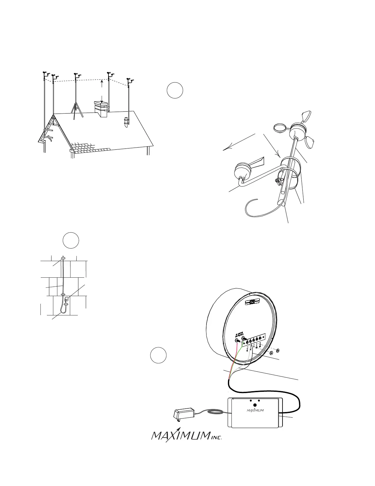
Follow the instructions supplied with the antenna mount
that you purchased and secure the mast to the mount.
5
8 FEET
CHIMNEY
MOUNT
VENT-PIPE
MOUNT
TRIPOD
MOUNT
WALL
MOUNT
EVE
MOUNT
MERLIN
INSTALLATION
WI-FI
DRIP
LOOP
CAULK
WIRE
CABLE
CLIPS
If the WI-FI SENSOR INTERFACE is to be inside form
a drip loop at least eight inches below the
point of entry into the building. Anchor any exposed
wire with insulated cable clips. Run the wire
into the building to the location where the SENSOR
INTERFACE will be located. Caulk any holes when done.
HOSE
CLAMP
EAST
MAST
“Z” SHAPED STUB
MUST BE ALIGNED
TO THE EAST
SOUTH
STUB
Samuel Barnett Boulevard
New Bedford, MA 02745
(508) 995-2200
Page 4
6
RED AND GREEN
WIRES FROM
INSTRUMENT
INTERFACE
BLACK
WIRE FROM
INSTRUMENT
INTERFACE
RED
A t t a c h t h e w i r e s t o t h e r e a r o f t h e b r a s s
INSTRUMENT as shown. The RED and GREEN
wires from the INSTRUMENT WI-FI INTERFACE
connect to the TERMINALS marked AC ADAPTER.
The WHITE wire connects to TERMINAL marked “1” and
the BLACK wire to TERMINAL marked “2”. (Do
NOT adjust the nuts that are already on the meter.)
RED
GREEN
GREEN
WEATHER INSTRUMENTS
WI-FI INSTRUMENT INTERFACE
Red: Instrument Power
Green: Instrument Power
White: Serial in
Black: Serial Common
WI-FI INSTRUMENT
INTERFACE
WHITE
WHITE
WIRE FROM
INSTRUMENT
INTERFACE
WHITE