Page 5 of 11 M-KIT118/119/120 Assembly Instrucons 181-03007
These instrucons must be followed exactly. Failure to follow these instrucons could damage the product or result in injury to persons
using or assembling the product. Maxon Furniture Inc. shall not be liable for any costs, loss, damage, expenses or injuries resulng from
failure to properly assemble the product in accordance with these instrucons.
Maxon Furniture Inc. Customer Service: 1-800-876-4274
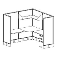
Installing the Panels
Slide/pry the Top Cap from each PL4848 Panel, 1.
being careful not to damage the parts (Figure
1).
CAUTION! The following steps may
require assistance to complete.
Posion two PL4848 Panels in their 2.
approximate installed locaon and level
by turning the Glides on the boom of the
PL4848 Panel frame with a ½” wrench.
On one PL4848 Panel, insert one Straight 3.
Alignment Bracket into the notch located on
the Panel’s edge at the boom of the PL4848
Panel frame (Figure 2).
Place one PLCP48 Corner Post on top of the 4.
Straight Alignment Bracket.
Connect the PLCP48 Corner Post to the PL4848 5.
Panel by sliding the plasc I-Beam Panel
Connectors down the grooves in between the
PLCP48 Corner Post and the PL4848 Panel’s
edge (Figure 3).
TIP! You will need three I-Beam
Panel Connectors to ll each groove
(six per connecon).
Using wire cuers or snips, trim the excess 6.
I-Beam Panel Connector length so that the
grooves are completely lled and ush with
the Panel frame top.
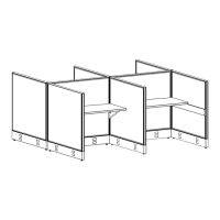
Place one PL4848 Panel against the PLCP48 7.
Corner Post at a 90° angle from the rst
PL4848 Panel creang an L shape.
Insert one Angle Alignment Bracket (Figure 2 8.
and Figure 4 on next page) into the slots of the
two PL4848 Panels being connected.
TIP! Use two slots near the boom
to help eliminate interference with
future accessory installaons.
Panel end
Top Cap
Figure 2
Figure 3
I-Beam Panel Connectors
PLCP48
Corner Post
PL4848
Panel
PL4848
Panel
Exterior Assembly View
Corner Post
Angle Alignment
Bracket
Straight Alignment
Bracket
Glide
Top View
I-Beam Panel
Connectors
Figure 1
 Loading...