PC4020 Design Notes
12
Step 6 - Write down how many Power Units each module will require.
Step 7 - Subtract the Power Units required for each module on each branch from the total Power
Units available.
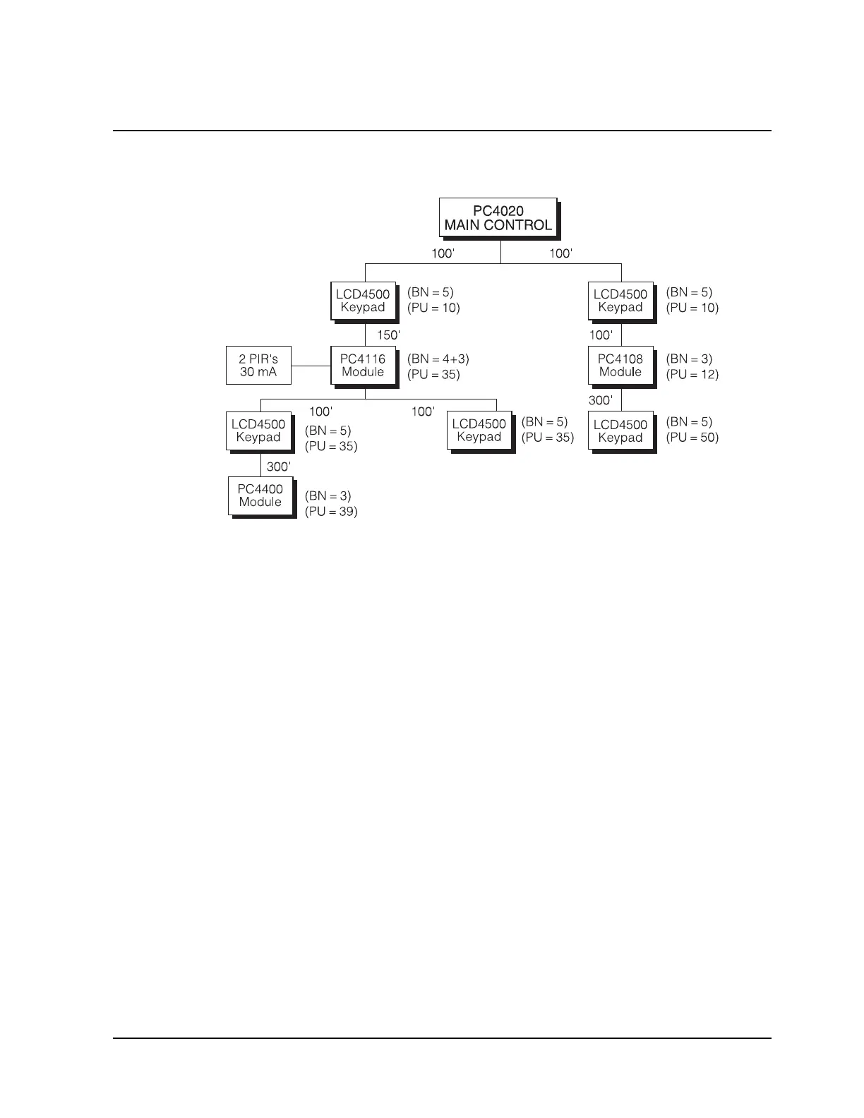
BRANCH #1
80 Power Units - 10 for the LCD4500 = 70 Power Units left
70 Power Units - 35 for the PC4116 = 35 Power Units left
Now something interesting happens. After the PC4116 the COMBUS branches again.
The total Power Units available for each of the sub-branches would be equal to the
Power Units remaining at that point (in this example 35).
SUB-BRANCH #A
35 Power Units - 35 for the LCD4500 = 0 Power Units left
0 Power Units - 39 for the PC4400 = -39 Power Units left
Sub-Branch #A will not work as it does not have enough power units!
SUB-BRANCH #B
35 Power Units - 35 for the LCD4500 = 0 Power Units left
Sub-Branch #B will work as the power units did not go negative!
BRANCH #2
80 Power Units - 10 for the LCD4500 = 70 Power Units left
70 Power Units - 12 for the PC4108 = 58 Power Units left
58 Power Units - 50 for the LCD4500 = 8 Power Units left
Branch #2 will work as the power units did not go negative!
Step 8 - Locate any PC4204 modules to correct any line loss problems.
In the above example one of the branches has excessive line loss and will require the
addition of a PC4204 module to correct the problem.