User Manual
EN
safety syMbols
High voltage
GND (ground)
Double insulation
Attention! Danger!
Low battery level
DC current
AC current
Fuse
properties
• LCD display: Maximum value display: 9999;
• Polarity display: automatic positive and negative
polarity indication
• Out of range signal: „OL”
• Power source: 2 x AAA 1.5 V
• Low battery indication:
Indicates that the
battery level is low, the battery required for the
operation of the device needs to be charged or
replaced.
• Automatic shutdown: If there is no operation
for 5 minutes, the instrument switches o
automatically, thus protecting the battery charge.
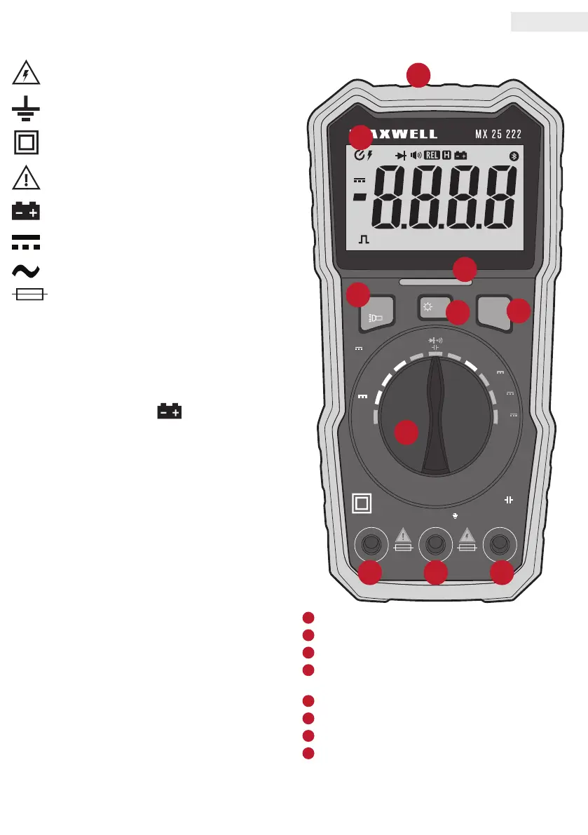
external strUCtUre
/H
SEL
MIN
MAX
REL
Live
NCV
TRUE RMS Auto Power Off
hFE
V
Hz/V
V
~
VΩmA
10A
MAX
MAX MAX
10A/250V 200mA/250V
COM
CAT.III 600V
BAT
hFEHz
~
T
R
U
E
R
M
S
4
0
0
0
C
o
u
n
t
s
DC
AC
~
Mk
hFE
OUT
nµmVA F
MIN MAX
Auto
ΩHz %
°C °F
1
2
4
5
88 8
6
3
7
OFF
Hz/%
µA
Hz
~
mA
Hz
~
10A
Hz
~
1.5V
3V/9V
B AT
Ω
1
NCV Non-Contact-Voltage detection/ Work light
2
LCD display
3
NCV light signal
4
SEL: Function selector button
Flashlight function
5
Data retention on display / Backlight on/o
6
MIN / MAX / REL
7
Function selection rotary switch
8
Input sockets