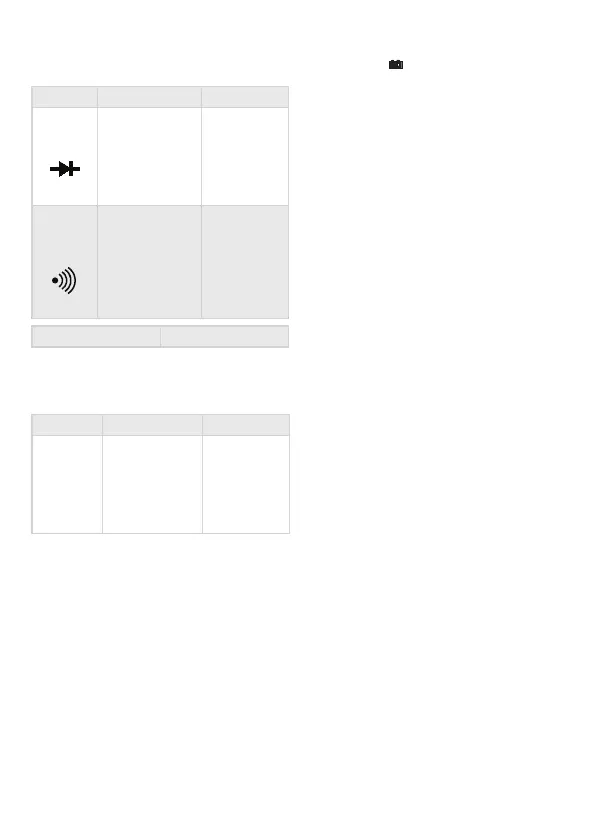
Dioda test
Function Description Test state
Diode's opening
voltage
measured
Opening DC
current appr.
1 mA
closing DC
voltage appr.
3 V
Beeping sound
indicates if
the resistance
between the
V/Ohm and COM
connectors is
below 90 Ω
Opening
voltage appr.
3 V
Overload protection 250 V DC/AC RMS
WARNING: Do not connect external power to
the connectors!
Transistor hFE test
Function Description Test state
h
FE
Measures the
amplication
factor of the
transistor
(0-1000)
(all types)
Base current
appr. 10 μA
V
CE
appr. 3 V
Contact phase detector function
• Set the function switch to TEST position.
• Connect the red wire into the V connector.
• Touch the wire to the measured point, BUT
MAKE SURE THAT YOUR FINGERS ARE BEHIND
THE FINGER PROTECTION AREA AT ALL TIMES!
If there is a phase present, the device will beep
continuously, the light below the screen lights up., and the
display shows ’1’ . If there is no phase, the display shows
’000’ .
IMPORTANT!
• Make sure when measuring like above that the
function switch is always in TEST position!
Usage
• Press long the POWER button. If the battery is
depleted, the symbol appears on the screen.
• Signs near the connectors warn about not
exceeding the shown values for inward current
or voltage to prevent damage to the inside
circuits.
• Set the function selection switch to the proper
position before measuring.
• If you are unsure about the range of the
measured value, switch to the highest available
one and go backwards from that until you
reach the proper range.
Background lighting B/L
Press long “HOLD/BL” key to turn on the
backlight, press it again to turn it o . It will be
auto o after 15 sec.
Note:
When the device is switch loses from its life time.
Holding data HOLD
During measuring the measured value can
be held by pushing the button 'HOLD'. When
you push this button again you can erase the
measured value from the display.
Automatic switch o APO
After you have nished using the device, it
switches o automatically after 10 minutes. The
automatic switch o function can be switched
on and o with pushing the button 'APO' long.
DC and AC current measuring
• Connect the black wire to the „COM” and the
red one to the „V/ Ω” connector.
• Set the function selection switch to the proper
V position and connect the wires to the power
source paralelly for the time of measurement.
Note:
• If you are unsure about the range of the measured value,
switch to the highest available one and go backwards
from that until you reach the proper range.
• If only „1” is displayed on the screen, it means overload.
Switch the range switch to a higher value.
• Do not connect voltage exceeding 1000V DC or 1000V AC
to the connectors. Results may be displayed with higher
values but this may lead to damage in the inside circuits.
• Do not touch the high voltage circuits while measuring.
DC and AC current measuring
EN
 Loading...