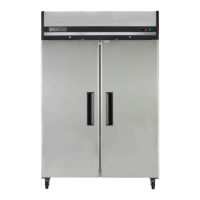
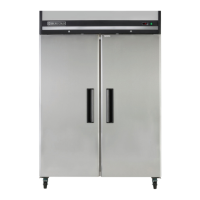
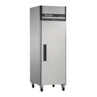
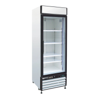
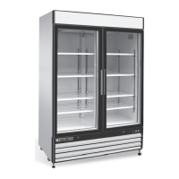
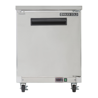
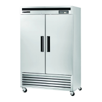
The Maxx Cold X-series is a line of reach-in refrigerators and freezers designed for commercial use. These units are intended for indoor use only and require careful installation and maintenance to ensure optimal performance and longevity.
Function Description:
The Maxx Cold X-series units are self-contained refrigeration systems that maintain specific temperature ranges for storing food and other perishable items. Refrigerators typically operate between 34°F and 38°F, while freezers maintain colder temperatures. The refrigeration cycle involves an evaporator coil, a condensing unit, and fan motors that circulate air within the cabinet. For refrigerators, evaporator fans run continuously, even when doors are open, and a defrost cycle occurs every 6 hours to clear ice from the evaporator coil. During defrost, the unit shuts off, and the controller displays a defrost symbol. Once the coil temperature reaches 41°F or after 20 minutes, the unit resumes operation. Anti-condensation heaters on the door frames work in conjunction with the compressor to prevent moisture buildup. For freezers, the controller powers the condensing unit and evaporator fan motors. Evaporator fans run when the coil temperature is below 35°F and also during door openings, but they cycle off during defrost. Similar to refrigerators, freezers undergo a defrost cycle every 6 hours, during which the unit is off, and electric heaters are activated to clear ice. The controller displays a defrost symbol, and the unit restarts once the coil temperature reaches 45°F or after 20 minutes.
Usage Features:
The units are equipped with an on/off switch located on the front of the top shroud, which glows green when the unit is on. The front panel features a digital display (Dixell controller) that shows the target set point and allows for various operations.
- SET button: Displays the target set point and, in programming mode, selects a parameter or confirms an operation.
- DEF button (UP arrow): Initiates a manual defrost when pressed for more than 2 seconds. In programming mode, it browses parameter codes or increases displayed values. It also displays the last temperature alarm.
- DOWN arrow: In programming mode, it browses parameter codes or decreases displayed values. It also displays the last temperature alarm.
- Key Combinations:
SET + UP and SET + DOWN: Used to lock and unlock the keyboard.SET + DOWN: Used to enter programming mode.SET + UP: Used to return to the room temperature display.
The display also includes various LED indicators for different functions:
- ON LED: Indicates compressor enabled, defrost enabled, or temperature alarm.
- Flashing LED: Indicates programming phase, anti-short cycle delay enabled, drip time in progress, or fans delay after defrost in progress.
The serial number, crucial for parts and service, is located inside the unit on the left-hand side near the top wall.
Maintenance Features:
Regular maintenance is essential for the efficient operation and longevity of Maxx Cold X-series units.
- Safety First: Always turn the on/off switch to OFF and disconnect the unit from the power source before performing any service, maintenance, or cleaning.
- Receiving and Inspecting: Upon delivery, visually inspect the exterior packaging for damage. If damage is noted, report it to the carrier immediately. Even if the exterior is undamaged, open and inspect for concealed damage, notifying the carrier verbally and in writing within 10 days of receipt. Check the compressor compartment housing and refrigeration package for secure lines and an intact base. Retain all crating material until inspection is complete or waived.
- Location: Units should be placed on a floor strong enough to support the total weight of the cabinet and contents (up to 1500 pounds when loaded). Good air circulation is vital; avoid hot corners or locations near stoves/ovens. It is recommended to install units at least 2 inches from any wall and with at least 12 inches of clearance above.
- Inside Cabinet: Do not overpack to allow for proper air circulation. Refrigerated air is discharged at the top rear and flows to the bottom. Obstructions can cause evaporator coil freeze-ups, temperature loss, or water overflow. Shelves have a rear turn-up to prevent items from blocking airflow. Fans are at the front of the coil, so avoid placing large boxes or tall stacks of product at the bottom.
- Leveling and Stabilizing: Ensure the cabinet is level from front to back and side to side using a level. If supplied with casters, the unit is already leveled, but the floor where it's located must be level. Lock the front wheels while in use for stability. If the unit has been laid on its side or back, allow at least 24 hours before start-up for compressor oil to flow back to the sump, preventing compressor failure and unit damage.
- Cleaning the Interior and Exterior: Use soap and warm water for general cleaning. For stubborn stains, use ammonia and water or a non-abrasive liquid cleaner. Always rub with the "grain" of the stainless steel to avoid marring the finish. Do not use abrasive cleaners, as they can scratch stainless steel and plastic and damage breaker strips and gaskets.
- Stainless Steel Care: To prevent discoloration and rust, clean stainless steel surfaces with alkaline-based or non-chloride cleaners. Chlorides, found in hard water, salts, and many household cleaners, can damage the protective film of stainless steel. Rinse thoroughly and dry completely after cleaning. Never use steel pads, wire brushes, or scrapers. For extreme stains or grease, use a non-abrasive cleaner and a plastic scrub pad. Stainless steel cleaners can restore and preserve the finish. Address early signs of breakdown (small pits/cracks) by cleaning thoroughly and applying stainless steel cleaners. Never use acid-based cleaning solutions, as acidic food products can also deteriorate the finish. Clean all food product from stainless steel surfaces.
- Cleaning the Condenser Coil: The condenser coil requires regular cleaning, at least every 90 days, or more frequently if debris accumulates quickly (e.g., every 30 days). For light dust, use a brush. For heavier buildup, use a vacuum or compressed air. For heavy grease, use de-greasing agents specifically for condenser coils, followed by compressed air. Failure to maintain a clean condenser coil can lead to high temperatures, excessive run times, continuous operation, compressor failures, and can void warranties. Never use a high-pressure water wash, as it can damage electrical components.
- Gasket Maintenance: Clean gaskets regularly with warm soapy water to prevent mold/mildew buildup and maintain elasticity. Avoid full-strength cleaning products that can make gaskets brittle. Never use sharp tools or knives to clean gaskets, as this can tear them. Gaskets are "Dart" style and can be easily pulled out of the groove and pressed back into place without tools.
- Doors/Hinges: Over time, hinges may loosen. If a door sags, tighten the screws mounting the hinge brackets to the frame. Loose or sagging doors can cause hinges to pull out, potentially damaging both the doors and hinges, possibly requiring qualified service.
- Drain Maintenance: Each unit has an internal drain that removes condensation from the evaporator coil, which then evaporates in an external condensate pan. Ensure the drain tube is connected from the evaporator housing to the condensate pan. If water collects inside or underneath the unit, check the drain tube's position and ensure it's inside the drain pan. Proper leveling of the unit is crucial for correct drainage. Keep drain lines free of obstructions, as food product can block them, causing water to back up and overflow.
- Door Replacement and Adjustment:
- Open the top shroud and swing it up until it rests on top of the unit.
- Open the door to about 100°-110° and keep it open.
- Loosen and remove the top screw of the self-closing cartridge and the three hinge screws, then slide the door up and out.
- Prepare the new door. Use a wrench to rotate the square head of the cartridge shaft approximately 120° in the closing direction. The hinge is now preloaded.
- Hold the door at about 100° from the closed position, insert the top hinge over the cartridge's square shaft, ensuring the hinge faces the cabinet. Insert and securely fasten the mounting screw.
- While still holding the entire door/hinge assembly at about 100°, slide it over the bottom hinge pin, ensuring alignment, then securely fasten the upper hinge.
- Allow the door to swing freely, ensuring it closes by itself without restriction.
- Plug in the unit and verify that the interior light turns off and the evap fan activates when the door closes.
- If needed, adjust the door height by adding plastic spacers/washers to the bottom hinge pin.
- Shroud Removal: To remove the bottom shroud (for bottom-mounted units only), loosen and remove the top screws, then slide the shroud up and out.