Installation and Operational Instructions for
ROBA
®
-brake-checker plus DC Type 028.600.2 (B.0286002.EN)
your reliable partner
27/03/2023 TF/GF
Page 7 of 14
Chr. Mayr GmbH + Co. KG
Eichenstraße 1, D-87665 Mauerstetten, Germany
Tel.: +49 8341 804-0, Fax: +49 8341 804-421
www.mayr.com, E-Mail: public.mayr@mayr.de
77
Inputs
Outputs
F/S 14
0 V
2)
(low) slow switch-off (SLOW)
24 V
2)
(high) fast switch-off (FAST)
START 13
0 V
2)
(low) Brake is not energised
24 V
2)
(high) Brake is energised
IN 11
0 V
2)
(low) Armature disk condition recognition activated
24 V
2)
(high) Armature disk condition recognition deactivated
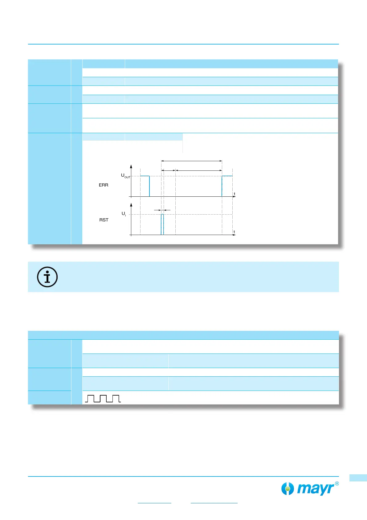
RST 12
0 V
2)
(low) Deactivated On activating the reset procedure, the ROBA
®
-brakechecker
restarts, and as a result, all pending signals (ERROR) are
deleted.
24 V
2)
(high) Activated
t
B
= 200 ms (Boot time)
t
C
= 400 ms (Calibration time)
t
R
= 600 ms (Reset time)
t
P
= 10 < 100 ms (Pulse time
must be less than 100
ms, greater than 10 ms)
(Output)
t
R
t
B
t
C
t
P
OUT 16
0 V
2)
(low)
Brake is not energised, movement of the armature disk for closing
the brake.
0.99 × U
I
(high)
Brake energised, movement of the armature disk for opening the
brake.
ERR
15
0.99 × U
I
(high) no errors
0 V
2)
(low)
Brake does not open or close, line interruption,
false detection
Warning
1)
Preventative function monitoring (Wear recognition and error
recognition)
1) Rectangular signal 10 Hz
2) DC = DC voltage
• All inputs without assignment (not connected) have the condition DC = 0 V (low).
• All inputs DC 24 V (high) have a current consumption of approx. 825 µA.
77