Do you have a question about the Mayr ROBA-stop-M 891 Series and is the answer not in the manual?
| Series | 891 |
|---|---|
| Operating Temperature | -20°C to +40°C |
| Application | Industrial braking systems |
| Voltage | 24 V DC |
| Protection Class | IP54 |
| Mounting | Flange mounting |
Overview of EU directives, conformity, and safety standards applicable to the product.
UK directives, conformity requirements, and UKCA marking for the product.
Crucial safety rules for installation, operation, and maintenance of the brake.
Listing of all relevant standards, directives, and regulations governing the brake.
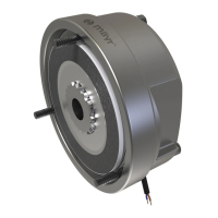
Visual diagrams showing the brake's construction and parts.
Comprehensive list of all brake components with item numbers.
Key technical specifications and braking torque values for different models.
Explanation of brake design, function, and what is included in delivery.
Requirements for installation environment and step-by-step mounting instructions.
Explains braking torque, its definition, and how to adjust it.
Procedures for conditioning friction linings and inspecting the brake.
Manual release procedure, torque-time diagram, and switching times.
Safety for grounding, fuses, and explanation of switching behavior.
Details on AC/DC switching, performance, and required protection circuits.
Method for measuring the air gap using a feeler gauge.
Guidelines for inspection, wear examination, and rotor replacement.
Details on friction material, hazards, protective measures, and brake cleaning.
Values for permitted friction work based on switching frequency and speed.
Instructions for proper disposal of brake components.
Common malfunctions, their causes, and recommended solutions.