EasyManua.ls Logo

Maytag Commercial MHN30PD User Manual

Maytag Commercial MHN30PD
16 pages
To Next Page IconTo Next Page
Page #1 background imageLoading...
Page #1 background image
FOR SERVICE TECHNICIAN ONLY - DO NOT REMOVE OR DESTROY
PART NO. W10340707A PAGE 1
IMPORTANT
Electrostatic Discharge (ESD)
Sensitive Electronics
ESD problems are present everywhere. ESD may damage
or weaken the electronic control assembly. The new control
assembly may appear to work well after repair is finished,
but failure may occur at a later date due to ESD stress.
Use an anti-static wrist strap. Connect wrist strap to green
earth connection point or unpainted metal in the appliance.
-OR-
Touch your finger repeatedly to a green earth connection point
or unpainted metal in the appliance.
Before removing the part from its package, touch the anti-
static bag to a green earth connection point or unpainted
metal in the appliance.
Avoid touching electronic parts or terminal contacts; handle
electronic control assembly by edges only.
When repackaging failed electronic control assembly in anti-
static bag, observe above instructions.
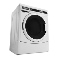
BASIC OPERATION OF EXPORT COMMERCIAL FL
WASHER, STARTING WITH MODEL 30
For additional information, see
www.MaytagCommercialLaundry.com
GENERAL USER INFORMATION
Scrolling ‘out of order’ showing in display, followed by a
failure or diagnostic code
This condition indicates the washer is inoperative.
0 Minutes’ showing in display
This condition indicates the washer cannot be operated. Coins
dropped or debit inputs during this condition will be stored in escrow
but cannot be used until normal operation is restored by opening
and closing the door. If a door switch fails, it must be replaced before
normal operation can be restored.
Cold Start (initial first use)
Washer is programmed at the factory as follows:
11 minute wash period
3 rinses (extra rinse not enabled)
$1.75 wash price (PD models)
$0.00 wash price (PN models)
Warm Start (after power failure)
A few seconds after power is restored, if a cycle was in progress
at the time of the power failure, RESELECT CYCLE’ will flash
in the display, indicating the need for a button press to restart
the washer.
Door Lock
The door will be locked when the cycle starts. The door will remain
l
ocked until the end of a cycle or approximately 2 minutes after a
power interruption.
Pricing
After the door is opened following the completion of a cycle,
the display indicates the cycle price (unless set for free operation).
As coins are dropped or debit inputs arrive, the display will change
to lead the user through the initiation of a cycle.
Free Cycles
This is established by setting the cycle price to zero. When this
happens, ‘SELECT CYCLE will appear rather than a cycle price.
Display
After the washer has been installed and plugged in, the display will
show ‘0 MINUTES. Once the washer has been plugged in and the
washer door opened and closed, the display will show the price. In
washers set for free cycles, the display will flash ‘SELECT CYCLE.
NOTE: Not displayed on washer as shown. Message scrolls
followed by the failure or diagnostic code.

Questions and Answers:

Maytag Commercial MHN30PD Specifications

General IconGeneral
BrandMaytag
ModelMHN30PD
TypeCommercial Washer
ColorWhite
Voltage120V
Wash ActionAgitator
Water Temperature SettingsHot, Warm, Cold
Energy Star QualifiedNo
Motor Size1/2 HP
Water Level SelectionsAutomatic
MaterialStainless Steel
Cycle OptionsMultiple cycle options available

Summary

Basic Operation of Commercial Washer

Door Lock Mechanism

The door locks at cycle start and remains locked until cycle completion or power interruption.

Pricing and Free Cycles

Explains cycle pricing display and how free cycles are indicated.

Display Functions and Indicators

Details initial display ('0 MINUTES') and subsequent price or 'SELECT CYCLE' indications.

Important Safety: ESD Precautions

General User Information

Initial and Post-Power Failure Starts

Covers factory settings for first use and restart procedures after power interruptions.

Control Set-Up Procedures

Using Keypads for Programming

Guide on using PERMANENT PRESS, DELICATES AND KNITS, QUICK CYCLE buttons for configuration.

Starting Operation Setup

Prerequisites for operation, including payment system or OPL kit.

Understanding Set-Up Codes

Explains navigation and use of specific set-up codes for washer functions.

Exiting Set-Up Mode

Diagnostic Guide

Washer Diagnostic Mode Operations

Procedures for entering diagnostic mode and initiating various test cycles.

Failure and Error Display Codes

CCU and MCU Error Explanations

Details CCU (F01) and MCU (F11) errors, including causes and recommended procedures.

Failure and Error Display Codes (Continued)

Water Fill and Drain Errors (F20, F21)

Explains issues related to no water detection and long drain times.

Door Lock and Temperature Sensor Errors (F22, F24)

Details door lock faults and water temperature sensor errors.

Failure and Error Display Codes (Continued)

Motor and Door Switch Errors (F25, F26)

Covers tachometer errors and door switch circuit faults.

Overflow and CCU/MCU Communication Errors (F27, F28)

Explains overflow conditions and communication failures between CCU and MCU.

Failure and Error Display Codes (Continued)

Door Unlock, Motor Overheat, Pump Errors (F29, F31, F33)

Addresses door unlock issues, motor overheating, and pump disconnection faults.

Load Detection and CCU/UIC Communication Errors (F34, F70)

Details load detection during cleanout and CCU/UIC communication failures.

Failure and Error Display Codes (Continued)

UIC and Coin Sensor Errors (F73, F74, d5, d13)

Explains UIC failures and coin sensor blockages (Coin 1 & Coin 2).

Debit Reader and Voltage Errors (d16, d9)

Covers Generation 2 debit card reader faults and low voltage detection.

Service Access Code

Diagnostic Test Modes

Keypad Functions in Diagnostic Modes

Overview of keypad functions for Failure Code Display, Flashing Mode, and Diagnostic Cycle modes.

Quick Overview Test

Manual Overview Test

Diagnostic Test Quick Guide

Keypad Function Table for Diagnostics

Summarizes keypad functions across different diagnostic sub-modes.

Help Mode

Help Codes Listing and Explanation

Provides a list of help codes and their meanings for troubleshooting.

Help Mode Submenu

Help Mode Symbols and Elements

Keypad Function in Help Mode Table

Maps keypad functions to results displayed in Help Mode, including symbols.

Diagnostic Tests

Motor and Sensor Continuity Tests

Guides for continuity testing of pump motor, drive motor, and water temperature sensor.

Transformer and Valve Checks

Resistance values for transformer and water valve checks.

Manually Unlocking Door Lock

Step-by-step instructions for manually unlocking the washer door.

Electronic Assemblies

Wiring Diagram

Troubleshooting Guide

Display and Input Issues

Troubleshooting for blank displays and unresponsive touch-pads.

Mechanical and Water Temperature Issues

Addresses washer vibration, drum rotation, and incorrect water temperature.

Related product manuals