5-7
Electrical Shock Hazard
Disconnect power before servicing.
Replace all parts and panels before operating.
Failure to do so can result in death or electrical shock.
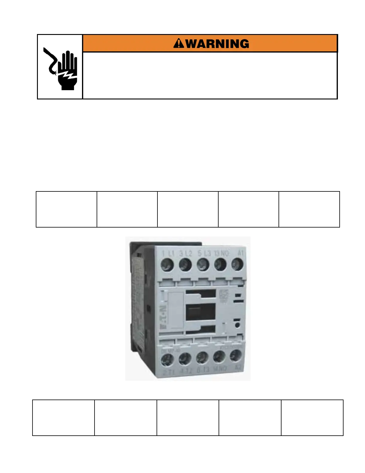
DRIVE CONTACTOR
The Drive Contactor supplies voltage to the VFD. For Single Phase models the Supply voltage
L1 is connected to Terminal 1 (L1) and Supply voltage L2 to Terminal 5 (L3). Output to power to
the VFD is connected to Terminal 2 (T1) and Terminal 6 (T3). For Three Phase washers Supply
voltage L1 is connected to Terminal 1 (L1), Supply voltage L2 is connected to Terminal 3 (L2),
and Supply voltage L3 is connected to Terminal 5 (L3). Output power to the VFD is connected to
Terminal 2 (T1), Terminal 4 (T2), and Terminal 6 (T3). Power to energize the Contactor Coil is sent
from the ACU to Terminals A1 and A2. Coil voltage is 230 VAC.
1 - L1 Supply
Power In
3 - L2 Supply
Power In
5 - L3 Supply
Power In
13 - Normally
Open Contact
(Spare - Not
Used)
A1 - Coil Power
2 - T1 Power to
VFD
4 - T2 Power to
VFD
6 - T3 Power to
VFD
14 - Normally
Open Contact
(Spare - Not
Used)
A2 - Coil Power
 Loading...