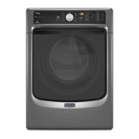
Do you have a question about the Maytag 111990" Automatic Dryers and is the answer not in the manual?
Details on using an appliance test meter, including calibration and reading resistance.
Explanation of how a clamp-on ammeter measures current and its diagnostic use.
Instructions on using a motor test cord to check drive motor functionality.
Guidance on measuring heating element and drive motor currents with an ammeter.
Procedures for testing heat contacts and the motor centrifugal switch using live or continuity tests.
Guidelines for checking voltage at the wall receptacle and general safety precautions.
Instructions on using the meter to measure air temperature for dryer diagnostics.
Lists potential causes and checks for a dryer that fails to start or run.
Identifies electrical issues that cause circuit breakers to trip or fuses to blow.
Diagnosing why the dryer runs but does not produce heat.
Addresses issues like wrinkles, harshness, or long drying times.
Diagnosing why the dryer fails to stop automatically after the cycle.
Checks for automatic shut-off failures in auto dry models, including thermostat issues.
Explains how electronic controls manage cycle termination and potential failure points.
Steps to isolate problems between control and sensor assemblies for proper shut off.
Procedures to check the dryness sensor for continuity and ground faults.
Checks for the neon bulb firing and relay coil operation in the electronic control.
Covers various non-standard dryer noises and buzzer malfunctions.
Diagnosing and identifying sources of thumping, ticking, and scraping sounds.
Checks for buzzer operation issues related to wiring, motor switch, or buzzer itself.
Addresses problems with the buzzer's duration, related to motor speed and switch reset.
Checks for buzzer issues specifically during the Press Care cycle setting.
Troubleshooting periodic buzzer operation during the permanent press cool down phase.
Explanation of how microprocessor boards control dryer functions using sensors and relays.
Steps to isolate problems in microprocessor-controlled dryers between control and controlled circuits.
Checks for the control circuit of the drive motor, including relay coil and voltage.
Tests the controlled circuit for the drive motor, focusing on relay switch contacts.
Checking the heater relay coil and voltage for electric dryers with microprocessor control.
Testing the heater relay switch contacts for continuity in electric dryers.
Explains the gas dryer heat control via microprocessor, without a separate relay.
Steps to diagnose why a gas dryer fails to produce heat.
Overview of microprocessor board functions and components like transformer, thermistor, and sensors.
Description of the step-down transformer's role in providing voltages to the microprocessor board.
Explains the varistor's function in protecting the microprocessor board from voltage surges.
Steps to check the transformer's primary and secondary windings for proper operation.
Diagnosing power loss by checking primary voltage at the transformer and power supply.
Checking continuity and voltage on the transformer's secondary windings.
Explanation of fault codes displayed by the microprocessor for various dryer malfunctions.
Details on fault code F-1, indicating a door circuit or board component failure.
Identifies fault code F-2 related to low temperature sensing or an open thermistor circuit.
Covers fault code F-3, indicating high temperature sensing or thermistor circuit issues.
Describes fault code F-4, indicating a motor transistor failure on the control board.
Explains fault code F-9, which indicates a low voltage condition detected by the system.
Steps required to clear fault codes after a problem has been corrected.
Instructions on how to gain access to the dryer's control panel for servicing.
Overview of the different types of controls used in Maytag dryers.
Identifies the four basic types of controls: Timer, Automatic, Electronic, and Microprocessor.
Explanation of how the electrical timer functions and controls cycle timing.
Explanation of how auto dry models operate based on moisture and evaporation rates.
Steps for removing and replacing the dryer's timer assembly.
Procedure for removing and replacing the timer motor from the timer assembly.
Instructions for removing and replacing the temperature selection switch.
Steps for carefully prying apart and removing the dryer's control panel.
Procedure for removing and replacing the buzzer assembly.
Instructions on how to adjust the buzzer tone using the slide lever.
Steps for removing and replacing the push-to-start switch.
Procedure for removing and replacing the auto-dry selection switch.
Steps for removing and replacing the press care option switch.
Detailed steps for removing the electronic control board, relay, and edgeboard connector.
Procedure for gaining access to and removing the dryness switch.
Steps to disconnect connectors and remove the microprocessor board and mounting panel.
Steps to disconnect wires and remove the transformer from the dryer top cover.
Procedure for removing the motor relay by disconnecting wires and screws.
Steps to remove the heater relay in electronic dryer models.
Diagram illustrating the components of the dryer's front panel assembly.
Instructions for removing screws and lifting/swinging the front panel away from the dryer.
Steps for removing the old door gasket and installing a new one.
Procedure for removing the dryer door by unscrewing hinges.
Steps to remove the door strike from the edge of the door panel.
Instructions for removing door hinges from both the door and the front panel.
Procedure for removing and replacing the door switch mechanism.
Steps for separating door halves, removing handle, and removing hinge screws.
Instructions for removing the old seal and installing a new front panel seal.
Diagram and description of the dryer's tumbler, rollers, belt, and interior light.
Explanation of the interior light's function and how to replace the bulb.
Steps for removing the light receptacle from the tumbler front.
Procedures for removing and testing the dryer's dryness sensor for continuity and ground faults.
Steps to remove the tumbler front, including bearing surfaces and ground wire.
Explains the lint filter switch's role in the 'Check Filter' warning and its mechanism.
Steps to disconnect the connector and remove the lint filter switch.
Procedure to check continuity of the lint filter switch by connecting/disconnecting the filter.
Steps for removing the outer half of the outlet duct and the front bulkhead.
Instructions for replacing tumbler front bearings and cork pads.
Procedure for removing the old seal and installing a new one on the tumbler front.
Steps to remove the front panel, tumbler front, and drive belt from the dryer.
Detailed steps for removing the tumbler and drive belt, including pulley access.
Step-by-step instructions for correctly installing the drive belt onto the pulleys.
Instructions for removing and replacing the tumbler clothes lifters, noting alignment tabs.
Steps for removing tumbler rear roller and bearing assemblies, including washers.
Procedure for replacing the felt seal on the tumbler rear, including installation tips.
Steps for removing the tumbler rear, including roller assemblies and heat cone.
Description of the three types of thermostats and their functions in heat control.
Steps to remove the 160° thermostat, located on the blower cover.
Procedure for checking the continuity of the 160° thermostat at room temperature.
Explanation of the thermistor's function as a temperature sensor in microprocessor systems.
Steps to remove the thermistor from the blower cover.
Procedure for checking thermistor resistance at different temperatures.
Explains the function of thermal fuses and cut-offs in preventing overheating.
Steps to remove thermal fuses and cut-offs from heat cone and blower cover.
Procedure for checking continuity of thermal fuses and cut-offs.
Description of multi-temperature thermostats and their cycling temperatures based on resistance.
Steps for replacing thermostats, including removal from blower cover.
Instructions for servicing the blower assembly, including impeller, housing, and seal.
Procedure for replacing the felt seal on the blower cover, using adhesive.
Steps to remove the blower cover by unscrewing it from the blower housing.
Instructions for removing the blower impeller from the motor shaft.
Steps for removing the blower housing from the motor mounting bracket.
Description of the exhaust duct pipe's connection to the blower housing and cabinet.
Diagram and explanation of the drive motor, motor switch, and idler assembly.
Explains the motor switch's role in changing motor windings and completing circuits.
Procedure for adjusting motor pulley position for proper alignment with the idler assembly.
Steps to remove the drive motor and base assembly from the dryer cabinet.
Instructions for removing and replacing the idler assembly, including lubrication notes.
Procedure for removing the idler pulley, noting fiber washers.
Diagram of the electric heating element, heat cone, and related safety components.
Steps to remove the heat cone, including shield, screws, and wires.
Detailed instructions for removing and installing the heating element, including insulators and clips.
Steps for removing and replacing the hi-limit thermostat, located on the heat cone.
Instructions for replacing the inlet duct, which connects to the tumbler rear.
Diagram and description of the gas valve, igniter, and radiant sensor system.
Explanation of the igniter's role in heating and igniting the gas.
Description of the radiant sensor's function, similar to a thermostat, in the ignition circuit.
Explanation of the gas valve's dual solenoids (holding and booster coils) and secondary coil.
Describes the sequence of events when the dryer calls for heat, including sensor and coil actions.
Details Phase I of the heat cycle where coils open Valve 1 and igniter heats up.
Describes Phase II where the igniter heats the sensor, opening its contacts and allowing ignition.
Explains Phase III where Valve 2 opens, releasing gas to the hot igniter for burner ignition.
Procedure for replacing the holding, booster, and secondary coils on the gas valve.
Steps for removing and replacing the igniter, with handling precautions.
Procedure for removing the radiant sensor from the heat cone.
Steps for removing and replacing the hi-limit thermostat on the heat source.
Steps to remove the gas valve and burner assembly, including wire harness and gas supply.
Instructions for removing the heat cone assembly from the gas dryer.
Procedure for removing the gas orifice using a 3/8" wrench.
Steps for replacing the inlet duct, which channels heated air into the tumbler.
Instructions for removing the console, top cover, and cabinet assembly.
Steps to remove the console by unscrewing it from the top cover.
Procedure for removing the top cover by releasing screws and pulling the wire harness.
Steps to remove the main cabinet assembly, including tumbler and base frame screws.
Recommendations for dryer placement, considering gas, electricity, and make-up air.
Essential rules for proper dryer venting to prevent fire hazards and ensure airflow.
Requirements for venting dryers located in bedrooms, bathrooms, or closets.
Guidelines on maximum lengths and bends for flexible metal exhaust ducting.
Guidelines on maximum lengths and bends for rigid metal exhaust ducting.
Recommendations for minimizing air resistance and ensuring efficient dryer venting.
Instructions for left side or base exhaust installations using accessory kits.
Guidelines for non-exhausted installations, emphasizing lint management and fire hazards.
Details on air flow resistance, pressure losses, and factors affecting drying times.
Procedure for adjusting the air shutter to achieve a proper blue flame for the main burner.
Guidelines for connecting the gas supply and converting between Natural and LPG gas.
Explanation of the automatic ignition system used to light the main burner.
Information on electrical service needs, codes, and grounding requirements for safe operation.
Details on the 120V, 60Hz, 15A electrical supply needed for gas dryer models.
Essential safety precautions and requirements for proper electrical grounding.
Guidance on installing an external ground wire when permitted by local codes.
References the National Electrical Code (NEC) for grounding and wiring.
References the Canadian Electrical Code (CEC) for grounding and wiring.
Information on the factory-installed ground strap for electric models.
Instructions for connecting gas and electric dryers to their power sources.
How to connect the power cord of gas models to a 120V, 3-prong grounded receptacle.
Guidelines for connecting electric models to a 30 amp receptacle.
Information on connecting Canadian models, noting power cord attachment and voltage conversion.
Details on connecting U.S. models, including voltage conversion kits and wiring requirements.
Provides details on alcove/closet installations, make-up air, and mobile home requirements.
Clearance and venting recommendations for installing dryers in alcoves or closets.
Specifies minimum area requirements for make-up air openings to ensure proper operation.
Guidelines for installing dryers in mobile homes, conforming to safety standards and anchoring.
Safety warnings regarding electrical shock and proper grounding when using gas dryers.
Warnings about drying foam rubber and items contaminated with flammable liquids.
Warning against allowing children to operate or play with the dryer.
Table detailing dimensions, capacity, motor, air flow, drum speed, and rotation.
Information on gas heat source capabilities and electric heat source wattage and circuit requirements.
Chart listing various dryer models with their control types and features.
Index of available electrical schematics and wiring diagrams for different dryer models.
Page numbers for electrical schematics of various electric dryer models.
Page numbers for electrical schematics of various gas dryer models.
Detailed electrical schematic for the DE9900 dryer model.
Wiring diagram illustrating the electrical connections for the DE9900 dryer.
Detailed electrical schematic for the DG9900 dryer model.
Wiring diagram illustrating the electrical connections for the DG9900 dryer.
Detailed electrical schematic for the DE9800 dryer model.
Wiring diagram illustrating the electrical connections for the DE9800 dryer.
Detailed electrical schematic for the DG9800 dryer model.
Wiring diagram illustrating the electrical connections for the DG9800 dryer.
Detailed electrical schematic for the DE9700 dryer model.
Wiring diagram illustrating the electrical connections for the DE9700 dryer.
Detailed electrical schematic for the DG9700 dryer model.
Wiring diagram illustrating the electrical connections for the DG9700 dryer.
Detailed electrical schematic for the DE8600 dryer model.
Wiring diagram illustrating the electrical connections for the DE8600 dryer.
Detailed electrical schematic for the DG8600 dryer model.
Wiring diagram illustrating the electrical connections for the DG8600 dryer.
Detailed electrical schematic for DE5910 and DE8500 dryer models.
Wiring diagram for DE5910 and DE8500 dryer models, illustrating electrical connections.
Detailed electrical schematic for DG5910 and DG8500 dryer models.
Wiring diagram for DG5910 and DG8500 dryer models, illustrating electrical connections.
Detailed electrical schematic for the DE8420 dryer model.
Wiring diagram illustrating the electrical connections for the DE8420 dryer.
Detailed electrical schematic for the DG8420 dryer model.
Wiring diagram illustrating the electrical connections for the DG8420 dryer.
Detailed electrical schematic for the DE8410 dryer model.
Wiring diagram illustrating the electrical connections for the DE8410 dryer.
Detailed electrical schematic for the DG8410 dryer model.
Wiring diagram illustrating the electrical connections for the DG8410 dryer.
Detailed electrical schematic for DE4910 and DE8300 dryer models.
Wiring diagram for DE4910 and DE8300 dryer models, illustrating electrical connections.
Detailed electrical schematic for DG4910 and DG8300 dryer models.
Wiring diagram for DG4910 and DG8300 dryer models, illustrating electrical connections.
Detailed electrical schematic for the DE8200 dryer model.
Wiring diagram illustrating the electrical connections for the DE8200 dryer.
Detailed electrical schematic for the DG8200 dryer model.
Wiring diagram illustrating the electrical connections for the DG8200 dryer.
Detailed electrical schematic for DE4000 and DE8000 dryer models.
Wiring diagram for DE4000 and DE8000 dryer models, illustrating electrical connections.
Detailed electrical schematic for the DG7600 dryer model.
Wiring diagram illustrating the electrical connections for the DG7600 dryer.
Detailed electrical schematic for the DE7800 dryer model.
Wiring diagram illustrating the electrical connections for the DE7800 dryer.
Detailed electrical schematic for the DG7800 dryer model.
Wiring diagram illustrating the electrical connections for the DG7800 dryer.
Detailed electrical schematic for the DE7400 dryer model.
Wiring diagram illustrating the electrical connections for the DE7400 dryer.
Detailed electrical schematic for the DG7400 dryer model.
Wiring diagram illustrating the electrical connections for the DG7400 dryer.
Detailed electrical schematic for the DE7500 dryer model.
Wiring diagram illustrating the electrical connections for the DE7500 dryer.
Detailed electrical schematic for the DG7500 dryer model.
Wiring diagram illustrating the electrical connections for the DG7500 dryer.
Detailed electrical schematic for the DE7400 Canada dryer model.
Wiring diagram illustrating the electrical connections for the DE7400 Canada dryer.
Detailed electrical schematic for the DE9900 Canada dryer model.
Wiring diagram illustrating the electrical connections for the DE9900 Canada dryer.
Detailed electrical schematic for the DE9800 Canada dryer model.
Wiring diagram illustrating the electrical connections for the DE9800 Canada dryer.
Detailed electrical schematic for the DE9700 Canada dryer model.
Wiring diagram illustrating the electrical connections for the DE9700 Canada dryer.
Detailed electrical schematic for the DE8600 Canada dryer model.
Wiring diagram illustrating the electrical connections for the DE8600 Canada dryer.
Detailed electrical schematic for the DE8410 Canada dryer model.
Wiring diagram illustrating the electrical connections for the DE8410 Canada dryer.
Detailed electrical schematic for the DE8420 Canada dryer model.
Wiring diagram illustrating the electrical connections for the DE8420 Canada dryer.
Detailed electrical schematic for the DE8200 Canada dryer model.
Wiring diagram illustrating the electrical connections for the DE8200 Canada dryer.
Detailed electrical schematic for DE4000 and DE8000 dryer models.
Wiring diagram for DE4000 and DE8000 dryer models, illustrating electrical connections.
Detailed electrical schematic for the DE7800 Canada dryer model.
Wiring diagram illustrating the electrical connections for the DE7800 Canada dryer.
Detailed electrical schematic for the DG7600 Canada dryer model.
Wiring diagram illustrating the electrical connections for the DG7600 Canada dryer.
Detailed electrical schematic for the DE7500 Canada dryer model.
Wiring diagram illustrating the electrical connections for the DE7500 Canada dryer.
Detailed electrical schematic for the DE7400 Canada dryer model.
Wiring diagram illustrating the electrical connections for the DE7400 Canada dryer.
| Brand | Maytag |
|---|---|
| Model Number | 111990 |
| Color | White |
| Power Source | Electric |
| Number of Temperature Settings | 4 |
| Wrinkle Prevention Option | Yes |
| Width | 29 inches |
| Height | 43 inches |
| Type | Automatic Dryer |


