3-WIRE SYSTEM CONNECTIONS
1. Loosen or remove center terminal block screw.
2. Connect neutral wire (white or center wire) of power supply cord to the center, silver coF
ored terminal screw of the terminaW block. Tighten screw.
3. Connect the other wires to outer terminal block screws. Tighten screws.
4. Tighten strain relief screws.
5. Insert tab of terminal block cover into slot of dryer rear panel. Secure cover with hold-
down screw.
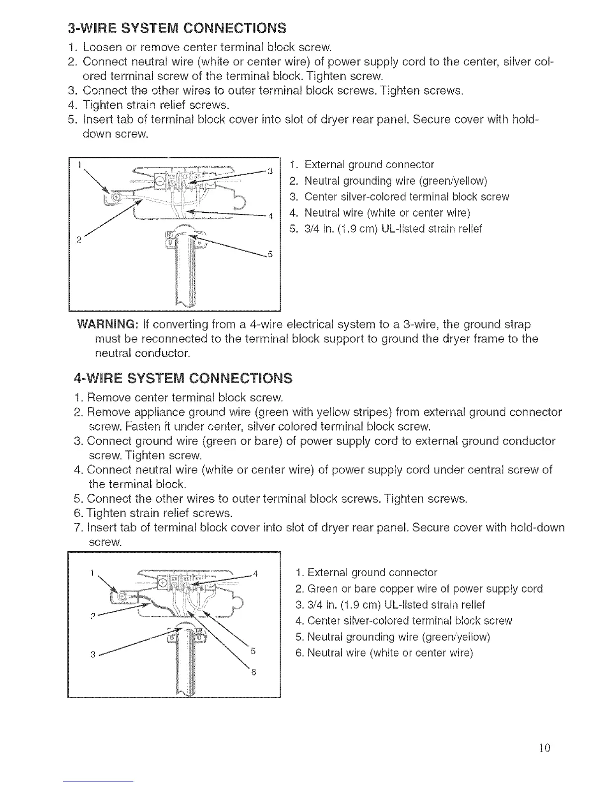
1. External ground connector
2. Neutral grounding wire (green/yellow)
3. Center silver-colored terminal block screw
4. Neutral wire (whRe or center wire)
5. 3/4 in. (1.9 cm) ULdisted strain relief
_5
WARNmNG: If converting from a 4_wire electrical system to a 3-wire, the ground strap
must be reconnected to the terminal block support to ground the dryer frame to the
neutral conductor.
4-WIRE SYSTEM CONNECTIONS
1. Remove center terminal block screw.
2. Remove appliance ground wire (green with yellow stripes) from external ground connector
screw. Fasten it under center, silver colored terminal block screw.
3. Connect ground wire (green or bare) of power supply cord to external ground conductor
screw. Tighten screw.
4. Connect neutral wire (white or center wire) of power supply cord under central screw of
the terminal block.
5. Connect the other wires to outer terminal block screws. Tighten screws.
6. Tighten strain relief screws.
7. Insert tab of terminal block cover into slot of dryer rear panel. Secure cover with hold-down
screw.
5
6
1. External ground connector
2. Green or bare copper wire of power supply cord
3.3/4 in. (1.9 cm) ULdisted strain relief
4. Center silver-colored terminal block screw
5. Neutral grounding wire (green/yellow)
6. Neutral wire (white or center wire)
10
 Loading...