Do you have a question about the Maytag MFI2568AEW and is the answer not in the manual?
General introduction to the repair process and its purpose.
Explains the technical cause of the fridge malfunction, focusing on capacitor issues.
Temporarily disable the ice door flapper to mitigate noise during repair.
Instructions for safely accessing and detaching the HV control board.
Guide to desoldering, replacing, and soldering new capacitors on the control board.
Instructions for re-mounting the repaired HV control board into the appliance.
Safety checks and procedures for testing the refrigerator's functionality post-repair.
Steps to reassemble the ice/water dispenser frame and reconnect its wiring.
This document provides a comprehensive guide for repairing the Maytag Ice2O French Door Refrigerator/Freezer Model MFI2568AEW, specifically addressing issues related to the High Voltage (HV) Control Board. It is intended for informational use and assumes a certain level of technical aptitude from the user, particularly regarding electronics and soldering. The guide emphasizes safety precautions due to working with wall-outlet level electricity.
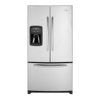
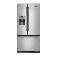
The Maytag Ice2O French Door Refrigerator/Freezer is a household appliance designed to store food at cold temperatures, featuring a French door design and an integrated ice and water dispenser. The core of its operation, particularly for the dispenser and compressor functions, relies on the HV Control Board. This board contains electronic components, including electrolytic capacitors, which are crucial for regulating the power supply to various parts of the refrigerator. The power supply converts rectified AC voltage from a transformer into a stable DC voltage, essential for the microcontroller (computer) and other electronic circuits to function correctly.
The refrigerator offers standard features expected of a modern appliance, such as ice and water dispensing from the front door. However, when certain components on the HV Control Board fail, these usage features are directly impacted. Common symptoms indicating a problem with the HV Control Board include:
The repair detailed in this guide aims to restore these essential usage features by fixing the underlying electronic issue.
The document outlines a specific maintenance procedure focused on replacing two failed electrolytic capacitors on the HV Control Board. This is presented as a cost-effective alternative to replacing the entire board, which can be expensive and subject to back-orders. The maintenance process involves several key steps:
Stopping the Flapping Noise (Optional): If the fridge is still cooling, users can temporarily disconnect the flapper door opener to stop the continuous flapping noise. This involves removing the drip tray, unscrewing two ¼" screws, gently prying and lifting the dispenser frame, and unplugging a small wire connector from the PCB. The frame can then be reassembled. If the fridge is no longer cooling, this step can be skipped, and the fridge should be unplugged immediately.
Removing the HV Control Board:
Replacing the Capacitors:
Re-installing the PCB:
Testing the Fridge:
The guide emphasizes the importance of static electricity precautions when handling the PCB and recommends wearing an electronics grounding strap if available. It also advises users who are uncomfortable with soldering or electronics to seek professional help.
| Brand | Maytag |
|---|---|
| Model | MFI2568AEW |
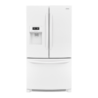
| Color | White |
| Freezer Capacity | 9.5 cu. ft. |
| Ice Maker | Yes |
| Water Dispenser | Yes |
| Counter Depth | No |
| Energy Star Certified | Yes |
| Type | Side by Side |
| Width | 35.75 inches |