FOR SERVICE TECHNICIAN ONLY - DO NOT REMOVE OR DESTROY POURLETECHNICIEN SEULEMENT - NE PAS ENLEVERNIDÉTRUIRE
NECÈIP11EGAPW10057361A.ONTRAP
o
W10057361A
TEST #4b ThermalFuse
ELECTRICDRYER: The thermal
fuse is wired in series with the
dryer drive motor.
GASDRYER:
The thermal fuse is
wired in series with the dryer gas valve.
ALLDRYERS:
1. Unplugdryerordisconnect
power.
2. Access the thermal fuseby
first removing the toe panel. See
Removing theToePanel, page 13;
and for thermal fuse location see
figure 11, page 9.
3. Usinganohmmeter, check the
continuity across the thermal fuse.
See figure11for location.
If the ohmmeter indicates an
open circuit, replace the failed
thermal fuse.
TEST #4c Thermal Cut-Off
If thedryer does not produce heat,
check the statusofthe thermal
cut-off.
1. Unplug dryer or disconnect power.
2. Access the thermal cut-off by
first removing the toe panel. See
Removing theToePanel, page 13.
3. Usinganohmmeter, check the
continuity across thethermal cut-off.
See figure 11, page9for location.
4. If the ohmmeter indicates an
open circuit, perform the following:
TESTN
o
4b Fusible thermique
SÉCHEUSE ÉLECTRIQUE: Le fusible
thermique est raccordé en série avec le moteur
d’entraînement.
SÉCHEUSEÀGAZ:
Le fusible thermique est
raccordé en série à l’électrovanne à gaz de la
sécheuse.
TOUTES LES SÉCHEUSES:
1. Débrancherlasécheuseoudéconnecter
la sourcedecourant électrique.
2. Ôterlepanneaudeplinthe pour accéder au
fusible thermique.Voir Déposedupanneau de
plinthe, page 13, et la figure 11, page9pour
la positiondufusible thermique.
3. Avecunohmmètre, contrôlerlacontinuitéà
traverslefusible thermique.Voir figure11pour
la position de ce composant.
Si l’ohmmètre indiqueuncircuit ouvert,
remplacerlefusible thermique défaillant.
TESTN
o
4c Coupe-circuit thermique
Si la sécheuseneproduit pasdechaleur,
contrôler l’étatducoupe-circuit thermique.
1. Débrancherlasécheuseoudéconnecter
la sourcedecourant électrique.
E
LECTRICDRYER:
R
eplace the
failed thermal cut-off and inlet
thermistor/high limit thermostat
assembly. In addition, check for
blocked or improper exhaust
system, or failed heat element.
GASDRYER:
Replace the failed
thermal cut-off and high limit
thermostat. In addition, check for
blocked or improper exhaust
system.
TEST #4d GasValve,
Gas Dryer
1. Unplugdryerordisconnect
power.
2. Access the gas valve by
removing the toe panel. See
Removing theToePanel, page 13.
3. Use an ohmmeter to determine if
a gas valve coil has failed.Remove
harness plugs. Measure resistance
across terminals.Readings should
match those showninthe chart
below. If not, replace coil.
2. Ôterlepanneaudeplinthe pour accéder
au coupe-circuit thermique.Voir Dépose
du panneaudeplinthe, page 13.
3. À l’aide d’un ohmmètre, contrôler la
continuité à traverslecoupe-circuit thermique;
voirsapositionàlafigure 11, page 9.
4. Si l’ohmmètre indiqueuncircuit ouvert,
exécuter les étapes suivantes:
SÉCHEUSE ÉLECTRIQUE:
Remplacer
l’ensemble thermistance d’entrée/thermostat
de température maximum. De plus, rechercher
une obstruction ou autre anomalie dans le
circuit d’évacuation de l’air humide, ou une
défaillance de l’élément chauffant.
SÉCHEUSEÀGAZ:
Remplacer le coupe-
circuit thermique défaillant et le thermostat
de température maximum. De plus, rechercher
une obstruction ou autre anomalie dans le
circuit d’évacuation de l’air humide.
TESTN
o
4d Électrovanneàgaz–
sécheuseàgaz
1. Débrancherlasécheuseoudéconnecter
la sourcedecourant électrique.
2. Ôterlepanneaudeplinthe pour accéderà
l’électrovanneàgaz.Voir Déposedupanneau
de plinthe, page 13.
3. À l’aide d’un ohmmètre, contrôler la
continuité à traverslabobinedel’électrovanne:
débrancher les conducteursetmesurer la
résistance entre les broches.Lesvaleurs
mesurées doivent correspondre aux indications
du tableau à gauche.Sicen’est paslecas,
remplacerlabobine.
1
2
345
Terminals Resistance ( )
1 to 2 1365 ± 60
1 to 3 560 ± 25
4 to 5 1325 ± 55
IMPORTANT: Be sure all
harness wires are looped
back through the strain relief
after checkingorreplacing coils.
Broches Résistance (
1 à 2 1365 ± 60
1 à 3 560 ± 25
4 à 5 1325 ± 55
IMPORTANT: Aprèslavérification
et la remiseenplace, vérifier que
tous les conducteurs sont
regroupés danslepasse-fil.
TEST#5 Moisture Sensor
NOTE: This testisstarted with the machine
completely assembled.
This testisperformed whenanautomatic cycle
stops too soon,orruns much longer than expected.
NOTE: Dryer will shut down automaticallyafter
2½ hours.
1. Activate the DiagnosticTest Mode and advance
past saved fault codes. See procedureonpage 1.
2. Open thedryer door. Thedryer will beep and an
alphanumeric number willbedisplayed.
3. Locate the two metal sensor stripsonthe face
of the lint screen housing. Usingawet clothorone
finger, jointly touch both strips.
If a beep toneisheard andanalphanumeric
numberisdisplayedonthe console, the sensor
passes the test. Go to step 9.
If a beep toneisnot heard,oracontinuous beep
toneisheard before touching both moisture strips,
continue with step 4.
NOTE: Over drying may be caused by a short circuit
in the sensor system.
TESTN
o
5 Capteur d’humidité
NOTE:On commencecetest surlamachine complètement
assemblée.
On exécutecetest lorsqu’un programme automatique prend fin trop
tôt, ou se poursuit plus longtemps qu’ilnedevrait.
NOTE:La sécheuse cesse automatiquementdefonctionneraprès
2½heures.
1. Activerlemodedetestdediagnosticetaller au-delà des codes
d’anomalie mémorisés.Voirlaprocédureàlapage 1.
2. Ouvrirlaporte de la sécheuse.Lasécheuse émetunsignal sonore
et un code alphanumérique s’affiche.
3. Identifier les deux rubans métalliquesducapteur d’humiditéà
l’avantdulogementdutamisàcharpie. Établir une liaison entre ces
deux rubans métalliques avecunlinge humideouavecundoigt.
Si l’appareil émetunsignal sonore et si un code alphanumérique
est affiché surlaconsole,lecapteur d’humidité estenbon état.
Passeràl’étape 9.
Si aucun signal sonore n’est émis ou si un signal sonore continu
est émis avantdetoucher les rubans métalliques, poursuivreà
l’étape 4.
NOTE:La durée excessive de la périodedechauffage peut être due
à un court-circuit danslesystèmededétection.
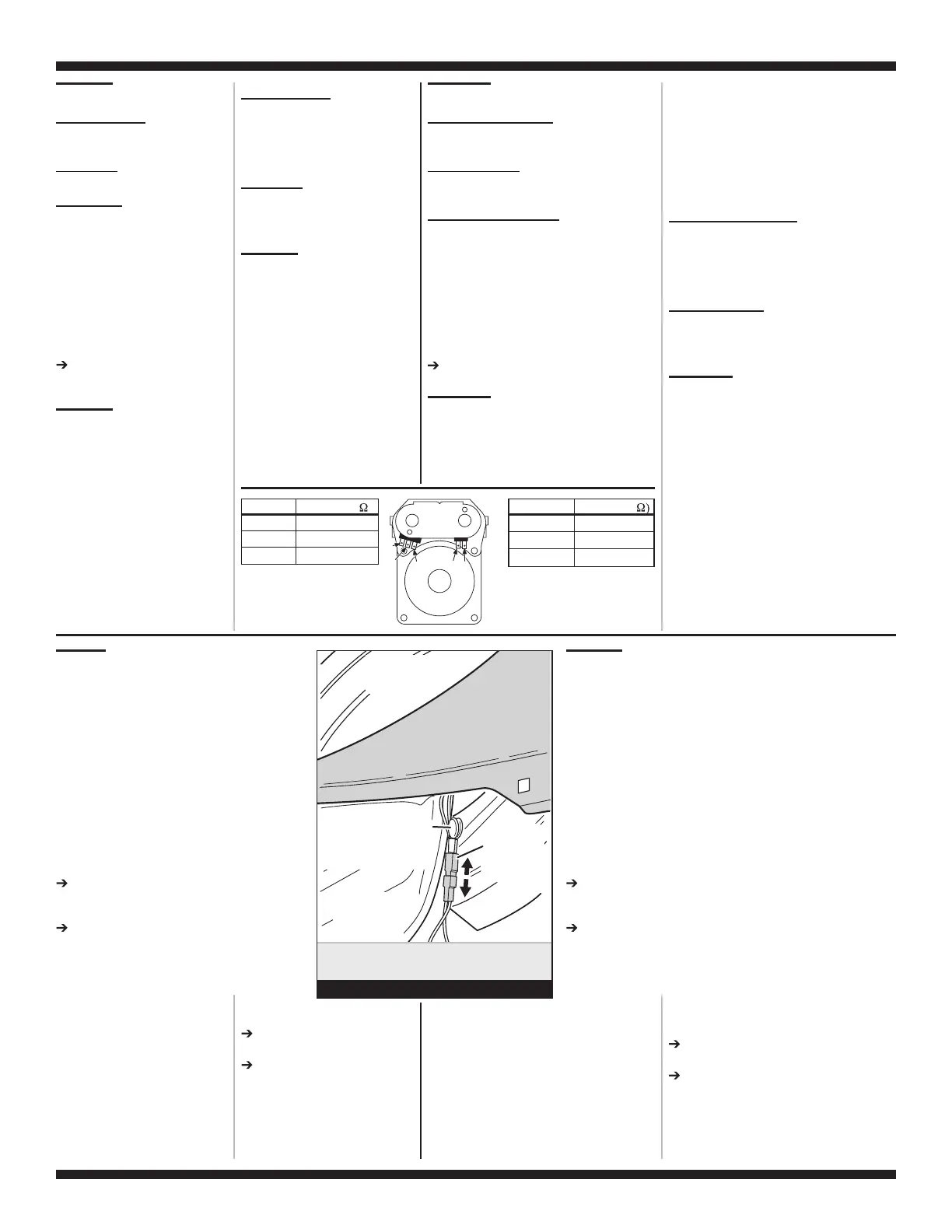
Harness
Connection
Blower Housing
Drum
Tambour
FRONT
AVANT
Logement du
ventilateur
Connexion
du câblage
MOVs
(Metal Oxide Varistors)
(Varistances en oxyde
métallique)
Disconnect sensor
from wire harness.
Débrancher le
capteur du câblage.
Figure 12
4. Access the moisture sensor
wiresbyremoving the toe panel.
SeeRemoving theToePanel, page
13. Disconnect the sensor wires
from the harness. See figure 12.
5. Access the machine control
electronics. See Accessing & Removing
the Electronic Assemblies, page 14.
Remove connector P13 from the
circuit board. Check the main
harness connections between the
sensor harness and machine
control forashortor open circuit.
Replace the main harness if
necessary.
If harnessisOK, continue with
step 6.
6. Access the moisture sensor
by removing the toe panel. See
Removing theToePanel, page 13.
Disconnect the sensor from the
wire harness. See figure 12.
4. Accéderaucâbleducapteur d’humidité:
ôter d’abordlepanneaudeplinthe.Voir Dépose
du panneaudeplinthe, page 13. Déconnecter
du câblage les conducteursducapteur. Voir
figure 12.
5. Accéderaumoduledecommande
électronique de la machine.Voir Modules
électroniques–Accèsetdéposeàlapage 14.
Débrancherleconnecteur P13 de la carte des
circuits. Vérifier les connexionsducâblage
principal entrelecâblageducapteuretle
moduledecommande de la machine pour voir
s’il y a un court-circuit ou un circuit ouvert.
Remplacerlecâblage principal si
nécessaire.
Si le câblage estenbon état, poursuivre
avec l’étape 6.
6. Accéderaucapteur d’humidité (enlever le
panneaudeplinthe).Voir Déposedupanneau
de plinthe, page 13. Déconnecterlecapteur
du câblage.Voir figure 12.
 Loading...