FOR SERVICE TECHNICIAN ONLY - DO NOT REMOVE OR DESTROY POURLETECHNICIEN SEULEMENT - NE PAS ENLEVERNIDÉTRUIRE
NECÈIP51EGAPW10057361A.ONTRAP
o
W10057361A
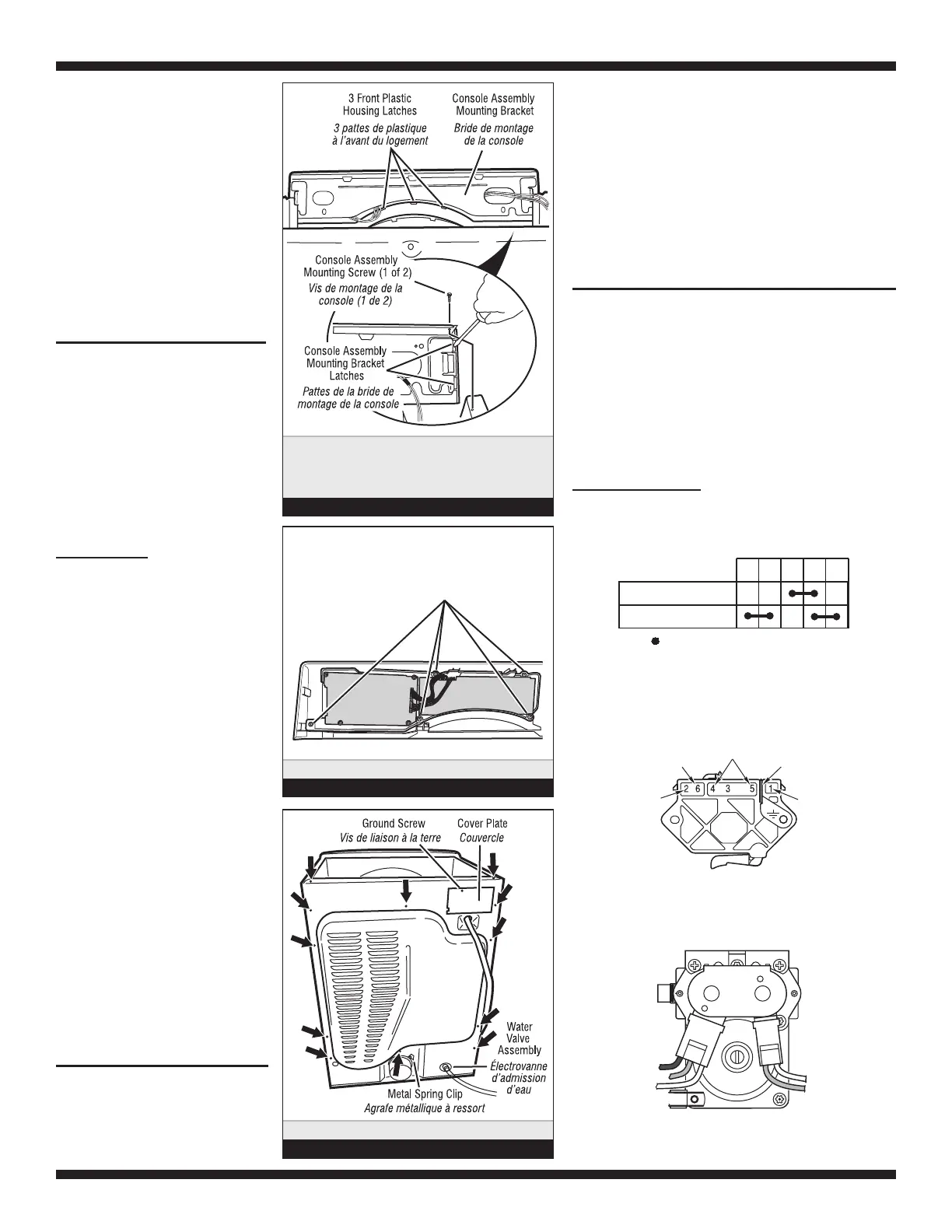
3. Slide the consoleupand offofthe
machine, gently unlatching the front three
plastic housing latches from the front door
trim section. See figures18and 19.
4. The console mounting bracketisfastened
to the console front panel with two latches at
both sidesofthe console assembly. Unlatch
the bracket gently withascrewdriver while
pulling the mounting bracket assembly out.
See figure 18.
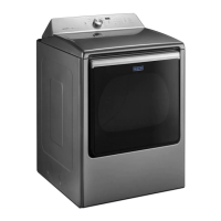
REMOVING THE BACKPANEL
1. Unplugdryerordisconnect power.
2. Remove the two rear screws from the top
panel, and slide the top paneltothe rear to
r
emove.
3. Remove the cover plate, disconnect the
power cord, and remove ground screw.
4. Remove the metal spring clip between the
back panel and the outlet. See figure 20.
5. Remove the ten screwsonthe rear, and
two screwsonthe topofthe back panel. Pull
the back panel off the machine.
ELECTRICDRYER:
In additiontothe above, remove the terminal
block from the back panel.
Remove the console panel
to access the console
electronics and housing
assembly.
Ôter le panneau de la
console pour accéder
à l’ensemble circuits
électroniques/carter.
Figure 18
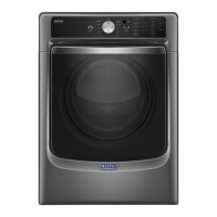
Black
Noir
Blue
Bleu
White
Blanc
White
Blanc
Blue
Bleu
Gas Valve, Gas Dryer
Électrovanne à gaz, sécheuse à gaz
1M 2M 3M 5M 6M
= Contacts closed/Contacts fermés
Contacts
Function/Fonction
Start/Démarrage
Run/Fonctionnement
Centrifugal Switch (Motor)
Contacteur centrifuge (moteur)
3. Faire glisserlaconsole verslehaut pour l’extrairedelamachine;
dégager doucement les trois pattesdeplastiqueàl’avant du
logement pour les séparer de la section avantdelagarniture de
porte.Voir figures 18 et 19.
4. La bridedemontage de la console est fixée surlepanneau avant
de la console avec deux pattesdefixationdepart et d’autredela
console. Utiliseruntournevis pour dégager doucement les pattes
de la bride toutentirant surlabridedemontage pour l’extraire.
Voir figure 18.
DÉPOSEDUPANNEAU ARRIÈRE
1. Débrancherlasécheuseoudéconnecterlasourcedecourant
électrique.
2. Ôter les deux vis arrièredupanneau supérieur, et faire glisser le
panneau supérieur vers l’arrière pour l’enlever.
3. Enleverlaplaquedecouverture; débrancherlecordon
d’alimentation; enleverlavisdeliaisonàlaterre.
4. Enlever l’agrafe métalliqueàressort entrelepanneau arrièreetla
bouchededécharge.Voir figure 20.
5. Enlever les dix visàl’arrière,etles deux visausommet du
panneau arrière. Tirer pour séparerlepanneau arrière de la machine.
SÉCHEUSE ÉLECTRIQUE:
En plus des opérations ci-dessus, séparerleblocdeconnexion
du panneau arrière.
Black-White
Noir-blanc
Lt. Blue
Bleu clair
Green-Yellow
Vert-jaune
Red
Rouge
Red
Rouge
Pluggable Drive Motor Switch
Contacteur du moteur d’entraînement enfichable
Remove 12 screws. Ôter 12 vis.
Figure 20
SOFTWARE COPYRIGHTED.
MANUFACTURED UNDER ONE OR MORE OF THE
FOLLOWING CANADIAN PATENTS:
LOGICIEL ASSUJETTI AUX DROITS D’AUTEUR.
FABRIQUÉ SOUS UN OU PLUSIEURS DES BREVETS
CANADIENS SUIVANTS :
1273387 1315539 2016304
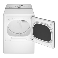
Remove five screws.
es.
Ôter cinq vis.
Figure 19
Location of five screws
that hold electronics assembly
Emplacement des cinq vis
maintenant le module électronique
5. The console electronics consists of two
printed circuit boards, connected by two
cables, mounted in a single electronics
assembly. The assembly is fastened to the
decorative piece by five screws. To remove
this assembly, remove the knob from the
front, remove the screws, and pull up on
the assembly. See figure 19.
5. Le moduleélectronique dela consoleestcomposé dedeux cartesde
circuits imprimés, connectés par deux câbles, montés en un module
électronique. Le module est fixé à la partie décorative avec 5 vis.
Pour enlever le module, retirer le bouton situé à l’avant et les vis,
et soulever le module en le tirant vers le haut.Voir figure 19.