Do you have a question about the Maytag MTB1954 and is the answer not in the manual?
Lists the specific Maytag, Jenn-Air, Magic Chef, and Admiral models covered.
Details electrical supply needs and safety precautions.
Explains the fundamental principles of the refrigeration cycle.
Outlines procedures for diagnosing system faults.
General information on replacing refrigerator compressors.
Covers the refrigerator's electrical system and component testing.
Explains the defrost timer's function and testing/replacement.
Information on different types of shelves and their servicing.
How to level the refrigerator for proper alignment and performance.
Criteria for determining if the cabinet door is in correct alignment.
General overview of testing ice maker components without removal.
How to adjust the water fill screw for ice maker operation.
Troubleshooting guide for a unit that won't run and has no light.
Diagnosing no cooling issues with continuous running.
Troubleshooting excessive noise while the unit functions normally.
Detailed specifications for the 15 cubic foot model.
Specs for 19 cu ft Auto Damper models.
Visual representation of the unit's electrical connections and components.
Diagram illustrating the path of refrigerant through the system.
| Brand | Maytag |
|---|---|
| Model | MTB1954 |
| Category | Refrigerator |
| Energy Star Certified | Yes |
| Defrost Type | Frost-Free |
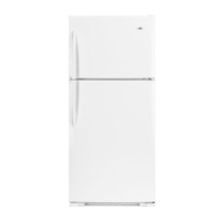
| Type | Top Freezer |
| Color | White |