W10162408
6
Component Testing Procedures
Component Electrical Testing (with ohmmeter)
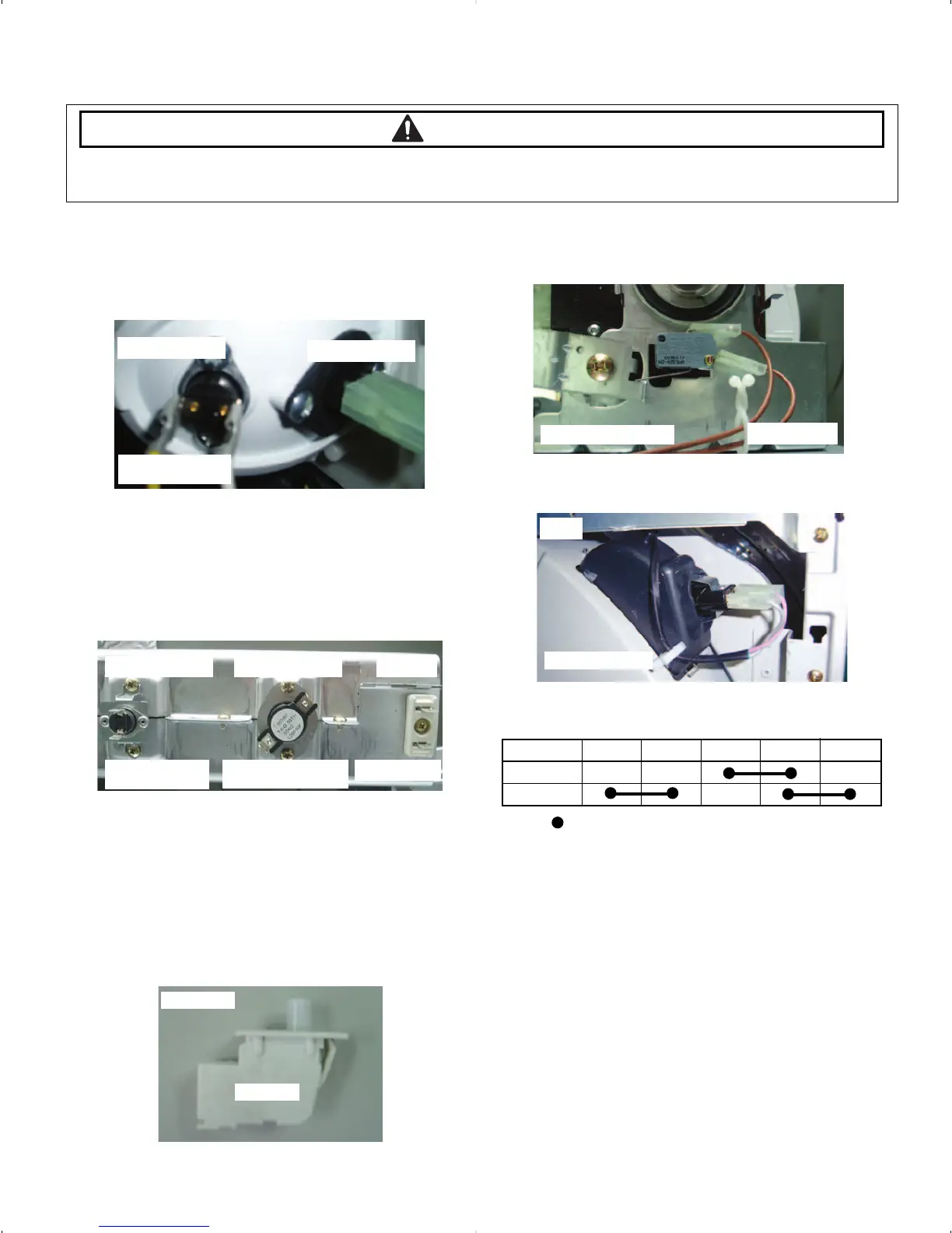
• Thermistor resistance 10K Ω @ 25°C 77°F PTC
(2P-Blue & Red wire)
• Thermostat 1 resistance < 1Ω (White & Yellow wire)
• Thermostat 3 resistance < 1Ω (Red & Black wire)
-If resistance is infinity, replace thermostat 3.
• Thermostat 2 resistance < 1Ω (Blue & Black wire)
-If resistance is infinity, replace thermostat 2.
• Heater resistance 10 Ω (Blue & Blue wire)
-If resistance is infinity, replace Heater.
• Measure resistance of the following terminal
1) Door switch button : out
Terminal : “COM” - “NC” (1-3) < 1Ω
Terminal : “COM” - “NO” (1-2) : ∞ Ω
2) Door switch button : in
Terminal : “COM” - “NC” (1-3) : ∞ Ω
Terminal : “COM” - “NO” (1-2) < 1Ω
• Belt Cut-off S/W
- Lever open : Resistance value < 1Ω
- Lever push : Resistance value : ∞ Ω
• Lamp resistance 80~100 Ω (Violet & gray)
• Motor (Electronic & GAS)
Contacts
WARNING
To avoid risk of electrical shock, personal injury or death; disconnect power to dryer before servicing, unless
testing requires power.
Function 1M 2M 3M 5M 6M
Start
Run
= Contact closed
THERMOSTAT 1
BELT CUT-OFF S/W
125V, 15A
320°F/160°C ,25A
thermal cut-off
260~210°F/127~99°C,
25A HI-limit
240V/5300W
120V/10W(E12)
125V/10A
185°F, 85°C, 25A
thermal cut-off
THERMISTOR
THERMOSTAT 3
DOOR S/W
THERMOSTAT 2 HEATER
LAMP





 To Next Page