4. Verify that continuity at terminal F is as indicated in the Terminal Voltage Table (Reference).
• If there is any malfunction, inspect the parts under "Inspection item(s)".
If the system does not work properly even though the parts or related wiring harnesses do
not have any malfunction, replace the flasher control module.
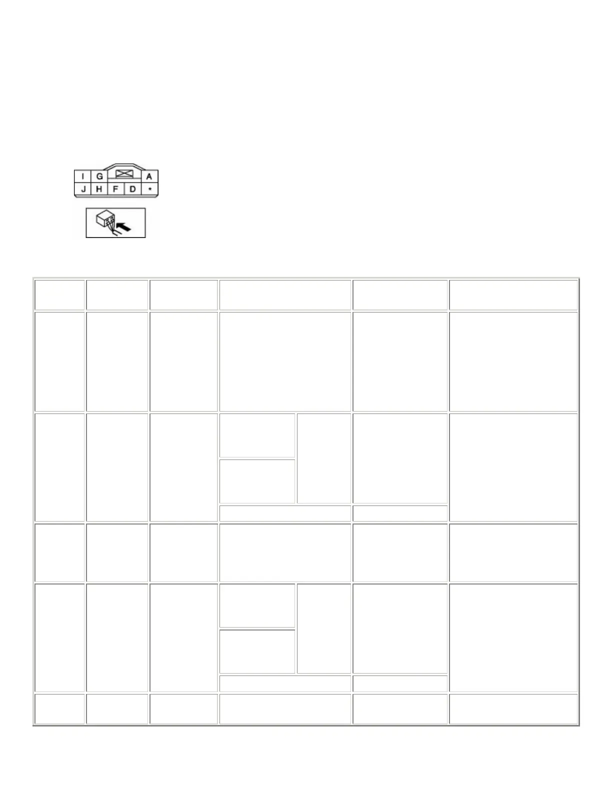
Terminal Voltage Table (Reference)
Terminal
Signal
name
Connected
to
Measured condition
Voltage
(V)/Continuity
Inspection item(s)
A
Power
supply
HAZARD
15 A fuse
Under any condition B+
• HAZARD 15 A
fuse
• Related wiring
harnesses
Turn light
switch (LH) is
on.
Hazard
warning
switch is on.
Turn
light (LH)
flashes.
Alternates
etween 1.0 or less
and B+
D
Flasher
control
module
output
Turn light
(LH)
Except above 1.0 or less
• Turn light (LH)
• Related wiring
harnesses
F GND
Body
ground
Under any condition:
Inspect for continuity to
ground.
Continuity
detected
• GND
Turn light
switch (RH) is
on.
Hazard
warning
switch is on.
Turn
light (RH)
flashes.
Alternates
etween 1.0 or less
and B+
G
Flasher
control
module
output
Turn light
(RH)
Except above 1.0 or less
• Turn light (RH)
• Related wiring
harnesses
H Hazard
Hazard
Hazard warning switch is
on.
1.0 or less