Operating Manual
Operation instructions Page13-6
13.3.2 Construction
The MB-OX-SE1 consists of the sensor and the special electronics separated by a gas-
tight NW40 clamp flange. The sensor is protected against physical damage by a protective
cage. The sensor leads are connected to the electronics by a vacuum-tight feed-through.
The electronics are contained in an airtight box mounted directly to the back of the NW40
flange.
13.3.3 Technical Data
1. In clean argon-atmosphere, without interfering gases like H
2
O or CO
2
2. In absence of reactive gases (contact MBRAUN Service for further advice)
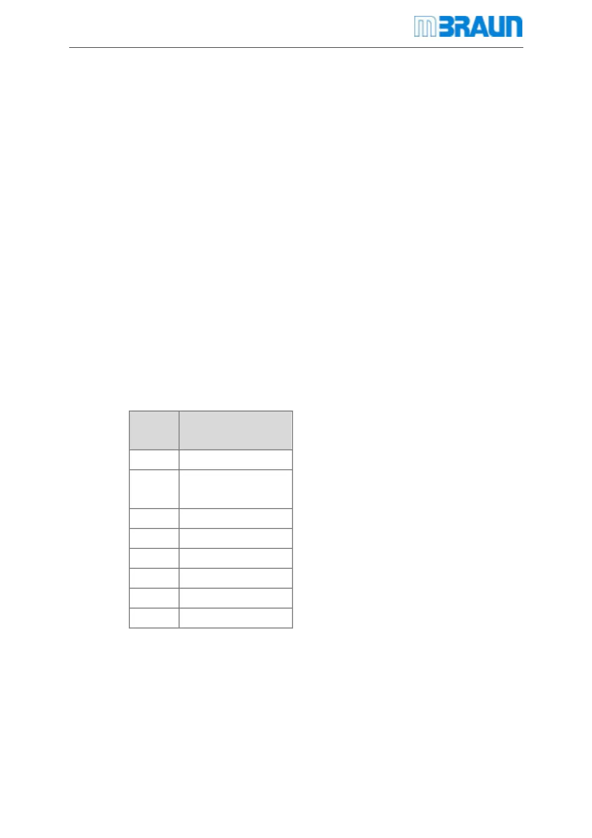
13.3.4 Connection
The connection for the Oxygen Sensor is made with an RJ45 (8-pole) Socket Connector. The
pin layout is shown in the table below.
Pin-No. Contact
1 Supply Ground
2
Switching ON/OFF 24
V
3 Signal Ground
4 Live bit (O2)
5 Not Connected
6 Signal 0 - +10 V
7 Supply +24 V
8 Supply Ground
Installation
The oxygen probe is mounted on an appropriate vacuum-tight NW40 flange by means of a
centring ring and a clamp. The plug connection to the control unit should not be made before
the whole box-system has been purged sufficiently with inert gas. The operation of the probe
 Loading...