13
REMOTE CONTROL OPTION
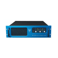
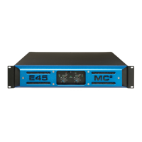
The MC750 is internally wired for remote control, which is easily achieved by installing the appropriate
interface/drive board during the manufacturing process, without any change to the amplifiers’
performance.
Description
The system is designed to replicate via Windows all the controls that are available on the front panel of
the amplifier (except power-on/off). This means that the volume can be turned up and down and the
channels can be linked/un-linked and muted/un-muted remotely.
Features
Up to 128 amplifiers can be ‘daisy-chained’ together from an RS485 port via an RS232-485
adaptor.
Amplifiers can be grouped together and controlled all at the same time within that group.
The front panel controls on the amplifiers can be ‘locked out’ so that they can only be controlled
from the computer. This allows the system to be set up to the client’s requirements and then made
secure against manual interference.
Two levels of security are available on the management control system through the use of
passwords, which permit a higher level access for the senior manager through one password and
more limited access at a lower level to a number of other ‘users’.
Full Windows software is available on www.download.at/mc2a
Wiring information
The interconnecting cable required is a twisted pair cable for short runs and a screened, low capacitance
data cable for long runs. The connectors are 9-way D-type and the wiring of this connector on the rear
panel complies with the standard two wire RS485 configuration as follows:
Signal Pin No.
A (+) 2 & 8
B (-) 3 & 7
Screen 5
All the ‘A’s should be joined together and all the ‘B’s joined together.
Pins 2 & 8 and 3 & 7 are joined inside the amplifier to ease the ‘daisy chain’ wiring.
The cable screen should be terminated at one place only, i.e. PIN 5 of the computer.