4-- 13© 2012 Mobile Climate Control T-299 Rev. 08/2012
Parallel
Misalignment
Angular
Misalignment
Figure 4-6 Belt Misalignment
Parallel adjustment is designed into a mount for final
alignment during the installation process. Parallel
misalignment is corrected by moving the driven
pulley (alternator or compressor) into alignment
with th e drive pulley. This can be done using several
methods. Spacing the component forward or
rearward by adding or removing spacers is the most
popular method used to achieve proper alignment.
Other methods such as sliding the component
forward or rearwards using slide plates and/or slots
in the main weldment are also used.
Angular m isalignment is often caused by to lerances
in several pieces, such as hardware to mou nting holes
and plates to components. Angular misalignment is
corrected by loosening the mounting hardware,
adjusting the compressor/alternator to the proper
angle and retightening the mounting hardware.
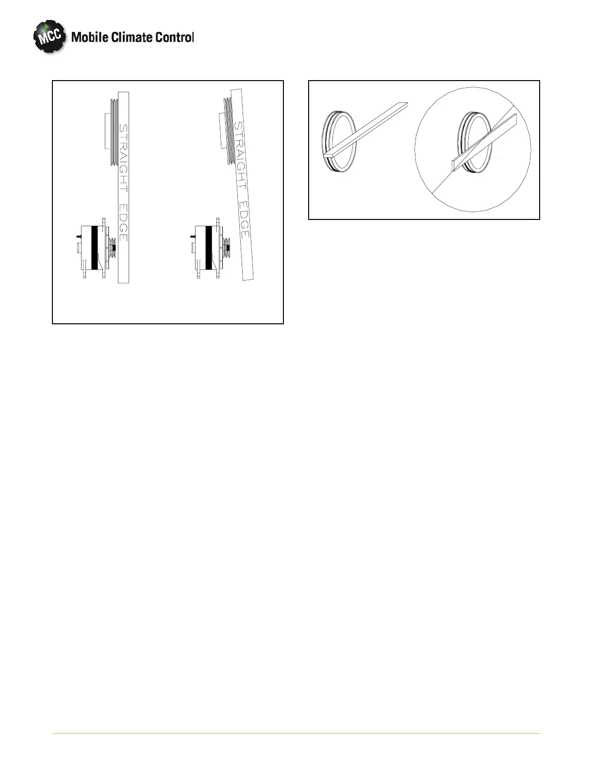
Correct
Incorrect
Figure 4-7 Straight-Edge Application
Proper use of a straight edge is illustrated in
Figure 4-7 . Never use a straight edge on the
wide/flat side, as th ey are n o t accurate. The thin edge
is a straight surface and the only accurate surface.
Thestraightedgemustbeflushacrossthefaceofthe
pulley. Then, to measure the alignment, lower the
other end down to the driven pulley(s). Adjustments
are made based on results of the aforementioned.
Note that the pulley rim width must be considered
when making the aforementioned measurements.
The next step is to lay the straight edge flush across
the face of the driven pulley. This is the best way to
determine angular misalignment. Again, adjust as
required. You should repeat this step for all pulleys
until acceptable alignment is achieved. No te th e
drive pulley is the primary guide for alignment. Do
not use idlers as a guide for proper component belt
alignment as bearing play could give you false
readings.
4.12.4 Drive Belt Tension Guidelines
Proper belt tension is essential for not only belt life,
but also the alternator and compressor life as well.
Heat is a major enemy o f compressors and
alternators that can cause unnecessary stress and
greatly reduce component life.
Listed in Table 4-9 are the examples specific to belt
tension concerns:
A. Under tension would promote belt slippage
causing excessive heat. Heat equ als premature
alternator and/or compressor failure.
B. Over tension could cause premature bearing
failure and excessive wear on drive and driven
components.
Proper belt tension is obtained by referring to
Table 4-9. Find the belt used and where applied
(compressor or alternator drive, Single ”V” or Ploy
”V” 4-8 ribs).
 Loading...
