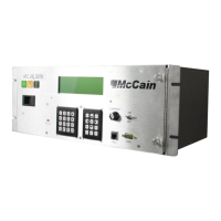
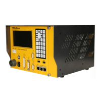
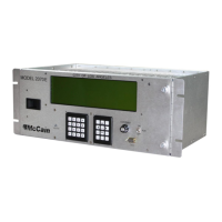
The ATC eX 2070N2 Controller is a ruggedized, multitasking field processor and communications system designed for a variety of traffic management applications. It can be configured for either rack or shelf mount. Its general purpose nature, open architecture, and modular design mean its functionality is dependent on the software loaded and the modules included. The controller is TS2 Type 1 compatible and fully complies with ATC (Advanced Transportation Controller) 5.2b standards and Caltrans Transportation Electrical Equipment Specifications (TEES) 2009 and Errata 1 January 21, 2010. While its primary function is intersection control, it can be used for a multitude of applications based on its software. The controller's Linux operating system provides a robust, flexible, and expandable platform compatible with multi-vendor application control software.
Benefits:
- NEMA TS2 Type 1 compatible.
- Compliant with current NEMA and ATC standards.
- The controller's multitasking operating system (OS) supports a variety of applications.
- Open architecture ensures compatibility with off-the-shelf products.
- Easily upgrades current intersection hardware.
- Compatible with Omni eX® intersection control software (available separately) for superior performance and advanced control.
Standard Features:
- Operating system: Linux, Version 2.6.22
- Modules (standard, included):
- 2070ATC CPU Module
- 2070-2N Field I/O module
- 2070-3B LCD/Front Panel Module
- 2070-4N(A) Power Supply
- 2070-7A Asynchronous Serial Communications module.
- Microprocessors: MPC8360E Freescale PowerQUICC II Pro microprocessor
- Backup real-time clock (RTC): Maxim DS1390
- Memory:
- 16MB Flash memory
- 128MB DDR RAM (expandable)
- 2MB non-volatile SRAM
- Applicable standards: Meets or exceeds Caltrans TEES 2009 standard and ATC (Advanced Transportation Controller) 5.2b standard.
Interfaces:
- Communication interfaces:
- Up to five SDLC ports
- Up to seven asynchronous ports
- ENET 1: 100 Base-T Ethernet switch, 1 uplink and 4 additional ports
- ENET 2: 100 Base-T Ethernet port dedicated for local communications (i.e. laptop or similar)
- Two USB ports
- Front panel interface:
- Display: 8 lines x 40 characters
- Keyboards: 3 x 4 navigation and 4 x 4 data entry keypads
- Cabinet interfaces:
- NEMA Port 1 C15S
- NEMA TS2 Type A connector
2070ATC CPU Module:
This module is the brain of the controller, fully compliant with the ATC 5.2b standard. It offers a wide variety of communication options, such as serial and Ethernet, for connectivity in any environment. Quick data transfers, firmware upgrades, and log retrievals can be done via USB. The Linux operating system provides a robust, flexible, open-architecture platform that supports third-party applications. The 2070ATC CPU is available with McCain's user-friendly, NTCIP compliant Omni eX intersection control software, which includes a comprehensive 'Help' feature for field technicians and supports all NEMA and NTCIP standard controller functions, along with enhanced features for maximum flexibility. The module consists of a host board, an engine board, and a faceplate.
Communication Interface Descriptions (CPU Module):
- Serial Port 1 (SP-1): General purpose port, available at the DIN-96 connector. Supports Asynchronous, Synchronous, HDLC, SDLC modes. Async rates: 1200, 2400, 4800, 9600, 19.2k, 38.4k (Optional: 57.6k, 115.2k). Sync rates: 19.2k, 38.4k, 57.6k, 76.8k, 153.6k. Interface pins include Transmit Data (O), Receive Data (I), Request To Send (O), Clear To Send (I), Carrier Detect (I), Transmit Clock Internal (O), Transmit Clock External (I), Receive Clock External (I).
- Serial Port 2 (SP-2): General purpose port, available at the DIN-96 connector. Operating modes and rates are identical to SP-1. Interface pins are also identical to SP-1.
- Serial Port 3 (SP-3): Used for in-cabinet devices, available at the DIN-96 connector. Operating modes and rates are identical to SP-1. Interface pins are also identical to SP-1.
- Serial Port 4 (SP-4): External user interface and general purpose, available at the DIN-96 connector. Operating modes and rates are identical to SP-1. Interface pins include Transmit Data (O) and Receive Data (I).
- Serial Port 5 (SP-5): Used for in-cabinet devices, available at the DIN-96 connector. Operating modes: Synchronous, HDLC, SDLC. Sync rates: 153.6k, 614.4k. Interface pins include Transmit Data (O), Receive Data (I), Transmit Clock Internal (O), and Receive Clock External (I).
- Serial Port 6 (SP-6): Front panel user interface, available at the DIN-96 connector. Operating modes and rates are identical to SP-1. Interface pins include Transmit Data (O) and Receive Data (I).
- Serial Port 8 (SP-8): General purpose, available at the C13S connector on the Front plate. Operating modes and rates are identical to SP-1. Interface pins include Transmit Data (O), Receive Data (I), Request To Send (O), Clear To Send (I), Carrier Detect (I), and Transmit Clock Internal (O).
- SPI (Serial Peripheral Interface): Supports Datakey and serial EEPROM interface. Located at Datakey's receptacle at Front plate and serial EEPROM on Host Board. Operating mode: Synchronous. Sync rates: Application specific. Interface pins include Master-Out-Slave-In (O), Master-In-Slave-Out (I), Clock (O), and four Select (O) pins.
- Universal Serial Bus (USB) Port: Facilitates data transfer to/from the CPU using USB memory devices as an alternative to a laptop computer. Two USB connectors at Front plate. Supports FAT16 file system providing 2GB storage. Interface pins include Data Line Positive (I/O), Data Line Negative (I/O), POWER_SWITCH Power Switch (O), and _OVERCURRENT Over-current (I).
- Ethernet Interface (ENET): Local and Network Communications. Two 10/100BASE-T Ethernet ports on Front plate, ENET1 (3) and ENET2 (1). Operating modes: Synchronous, Manchester-encoded, and Differential. Sync rates: 10M, 100M. Interface pins for both ENET1 and ENET2 include Transmit Data Positive (O), Transmit Data Negative (O), Receive Data Positive (I), and Receive Data Negative (I).
Host Board:
This board provides the mechanical and electrical interface to the Engine Board. All circuitry related to power, communications, control, and signal conditioning is provided to the Engine Board. It includes DIN-96 connector, C13S Connector circuitry, control signals circuitry (Power Down, Power Up, Linesync and CPU Reset), receptacles for engine board installation, voltage regulators, RS-485 line driver/receiver circuitry, backup circuitry, Ethernet switches, USB switch, Datakey circuitry, Active LED circuitry, A2-A3 installation detection circuitry, and ESD protection.
Engine Board:
The Engine Board is the brain of the ATC Controller, concentrating all computational functions. It comprises four sub-systems: Processor, Memory, Communications, and Reset management. It meets ATC 5.2b specifications for interchangeability. The engine provides two 50-position interface connectors and four standoff holes for installation onto a Host Board.
- Microprocessor: The PowerQUICC II Pro Processor MPC8360 handles all operations and processes, including running application software, administering buses, managing memory, controlling communications (seven serial ports, two Ethernet ports, one USB port, one SPI bus, one local I2C bus, one BDM bus), and monitoring/setting I/O signals.
- Memory:
- System memory: DDR2 memory, default 128 MBytes (expandable to 256, 512, 1024Mbytes).
- FLASH memory: 16 MBytes of non-volatile NOR FLASH for OS software and remaining capacity for user application programs.
- SRAM (with backup): 2 MBytes of non-volatile SRAM with supervisory circuit for power supply and write protection. The Engine Board provides standby power to the on-board circuitry during power failure.
- RTC: Real time clock with 100ms resolution, connected to Vcc and standby voltage supply. It monitors the RTC time and updates the RTC if power failure occurs.
- Communications: The PowerQUICC II Pro Processor MPC8360 handles all communications, including seven serial ports (SP-1 to SP-8), two Ethernet ports (ENET1 and ENET2), one USB port, one SPI bus, one local I2C bus, and one BDM bus.
- Reset Management: The Engine Board provides an active-low, +5VDC, output signal called CPU_RESET, generated by the CPU Reset line circuit (an OR gate receiving hardware and software reset signals).
- Hardware Reset: Active-low signal from the Processor upon an input signal representing a reset condition (output of a two-input AND gate, with POWERUP and supervisory circuit output as inputs). POWERUP is an active-low Power Supply's control signal triggered by a long power outage.
- Software Reset: Active-low signal from the Processor upon a reset command from the application software.
2070-2N Module, Field I/O Module:
This module serves as an interface between the Controller and the external world via Serial port 3 at the C15S connector. It provides a TS2 Type 1 compatible SDLC interface for controlling TS2 BIU Units. Fault monitor logic output is via SP-5 on output O78 to the NEMA TS2 Malfunction Management Unit. The module includes a C15S Connector (for SP-3), a 10 Pin "A" Connector (for AC input and Fault monitor output), a NEMA 5-15 Receptacle (for 2070-4 Power supply unit), a 2070 Type board, and a 4X face plate.
2070-7A Module, Async Communication Serial Board:
This hot-swappable module extends and isolates the Controller's serial communication ports (A1/A2 slots) to the rear panel for field connections. It provides two 9-position D-sub female connectors (C21S for channel 1, C22S for channel 2) with opto-isolated communication channels and LED indicators for Tx and Rx status. Serial ports SP-1/SP-2 are supported if installed in A2, and SP-3/SP-4 if installed in A1. Both channels can be manually disabled, and channel 2 can be disabled by the "C50 enable" signal. The module includes a 2070 Type board and a 2X face plate.
2070-3B Module, Front Panel Assembly:
This module provides the user interface via keypads and an LCD display. It has serial port SP-4 available through C50S and C50J connectors for terminal connection, an ACTIVE LED, an AUX switch, and an LCD contrast knob. The assembly serves as a swinging door to cover the back of the Chassis and Serial motherboard. It includes an 8-line by 40-character display, 4x4 alphanumeric keyboard, 3x4 cursor and symbol keyboard, C50S and C50J connectors, AUX switch, ACTIVE LED, P2 and P3 connectors, RESET switch, sliding latch, two thumbscrews, a sub-assembly board, and a metal panel.
2070-4N(A) Power Supply Module:
This module is the power supply for the Controller. It receives AC line input and provides power outputs (+5VDC @ 10A, +/-12VDC @ 0.5A, isolated +12VDC @ 1A, +5VDC Standby) and control signals (LINESYNC, ACFAIL/POWER DOWN, POWER UP/SYSTEM RESET) at PS1 and PS2 connectors. It complies with TEES 2009, is self-contained, convection-vented, and includes LED indicators, ON/OFF Power switch, Slow Blow fuse, a sub-assembly control board, small power supply modules, harnessing, and metal panels.
General Specifications:
- Style: Caltrans 2070
- Dimensions: 7" H x 19" W x 13" D (rounded to the nearest inch)
- Form factor: Shelf mount or 19" EIA (Electronics Industry Alliance) rack mount
- Weight: ± 12.3 lbs (based on final module selection)
- Power:
- AC voltage: 85 VAC to 135 VAC
- Frequency: 60 Hz (± 3 Hz)
- Power supply output specifications:
- +5.0 VDC: 1.0 A - 10.0 A
- +12.0 VDC Serial: 0.1 A - 0.5 A
- -12.0 VDC Serial: 0.1 A - 0.5 A
- +12.0 VDC ISO: 0.1 A - 1.0 A
- Environment:
- Operating Temperature: -37° C to +74° C
- Humidity: 0 to 95% (non-condensing)
Maintenance Features:
- CPU Module Installation: Turn off the controller, slide the 2070ATC CPU into slot A5, press into the backplane, and tighten thumbscrews.
- 2070-2N Module Installation: Normally attached to the Controller. If not, turn off the controller, slide into slot A3, press into the backplane, tighten thumbscrews, and plug the power cord into NEMA 5-15 receptacle.
- 2070-7A Module Installation: Hot swappable. Turn off the controller, verify jumpers, slide into slot A1/A2, press into the backplane, and tighten thumbscrews.
- 2070-3B Module Installation: Turn off the controller, install on the front of the controller and attach to the chassis, tighten thumbscrews, insert ribbon cable connector into P3, and ensure 2070-3B is correctly opened, closed and secured.
- 2070-4N(A) Module Installation: Turn off the 2070-4N (A) module, slide into its compartment from the back of the Chassis unit, attach by tightening TSD #3 devices, plug PS2 harness, plug AC cord, and turn on the power switch.
- Adjustments: The power supply module has four factory-set adjustments (Power Fail: 85VAC ±2VAC, Power Recovery: 90VAC ±2VAC) via a potentiometer. Each power module has a potentiometer for DC voltage level adjustment.