30125-70 Rev. 1.0 | 18NOV2021
Page 2
INTRODUCTION
1.0 INTRODUCTION
1.1 Description
Ultra Mag meters are available with integral or remote mount converters. Standard display features include forward,
reverse and net ow totalizers, ow rate, alarm monitoring, and automatic self diagnostics to ensure integrity. All data and
values are in selectable units of measurement. System compatibility is assured with a choice of current, pulse and serial
data. Please refer to the converter manual provided with your meter.
Ultra Mag operating parameters are set via the electronics keypad. The software features multilevel password protection
capability to prevent inadvertent program or setting changes. Data is stored in nonvolatile memory.
The anged end tube design permits use in a wide range of applications. The fabricated tube is stainless steel with steel or
stainless steel anges and incorporates the UltraLiner, an NSF approved fusion-bonded
epoxy liner.
1.2 Uncrating
The shipping crate contains the following items:
Electromagnetic meter assembly with grounding wire attached
Converter cable (attached to meter)
Signal converter
Grounding rings
Ground wires (2)
User manuals for both the sensor and converter
Installation hardware (2” & 3” only)
Gaskets (4) (2” & 3” only)
When uncrating the Ultra Mag, any damage due to rough or improper handling should be reported to the transportation
rm and McCrometer. If for any reason it is determined that the unit or parts of the unit should be returned to the factory,
please contact McCrometer for clearance prior to shipment. Each unit must be properly crated to prevent any further
damage. The factory assumes no responsibility for equipment damaged in return shipment due to improper packaging.
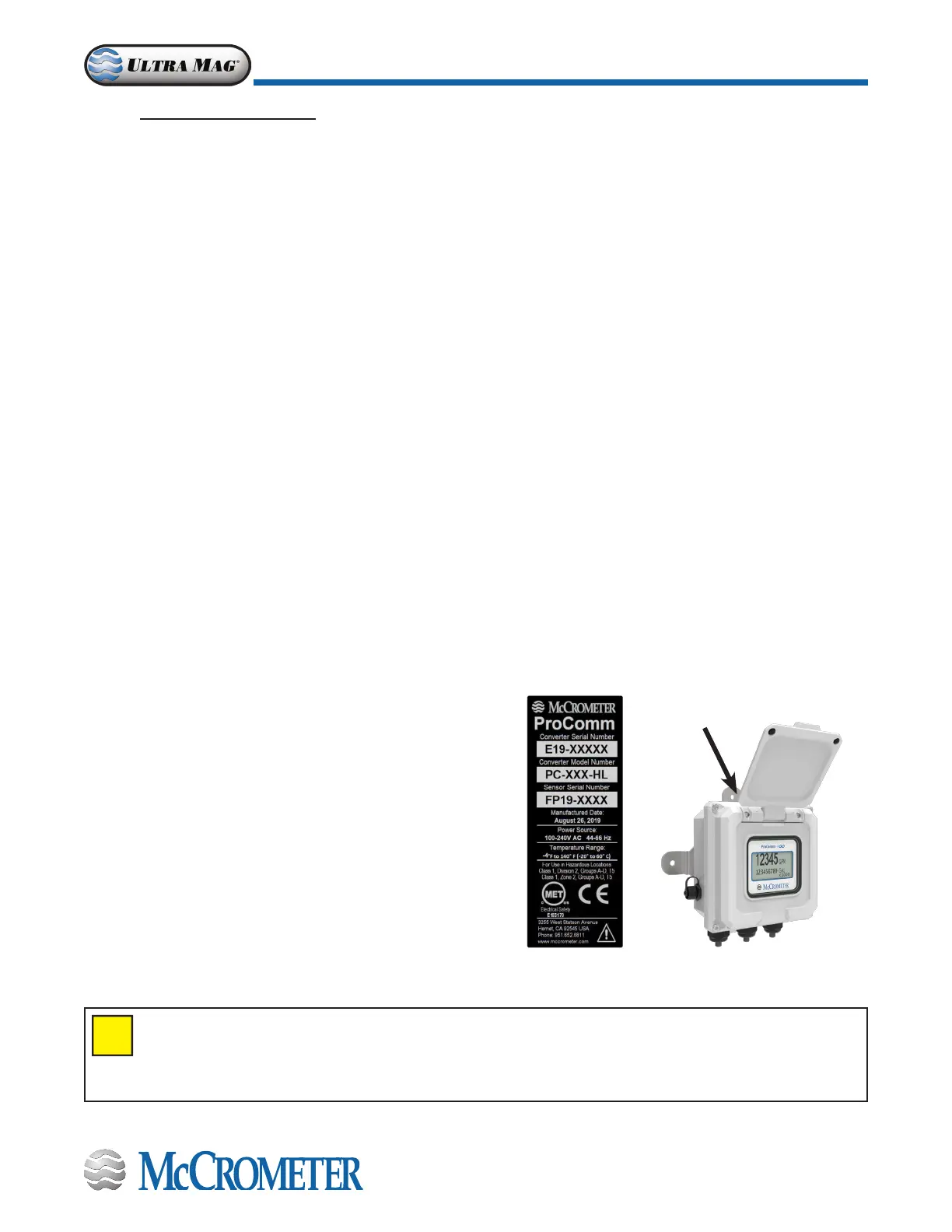
1.3 Serial Numbers
The converter and sensor are supplied as a matched system.
Verify the meter serial numbers on both the converter and sensor
match. This will insure a properly calibrated system.
The tag on the side of the converter has the converter model
number, the converter serial number and the meter serial
number, which is calibrated to the converter. An example is
shown at right.
Figure 1. Converter serial number tag
IMPORTANT: Verify the meter serial numbers on both the converter and sensor match. This will insure a
properly calibrated system. The meter serial number is located on a plate on the body of the sensor, and
the converter serial number and the meter serial number are located on a label on the side of the converter.
Insure the meter serial number on the sensor and the converter tags match.