McCULLOCH
CHAIN SAW
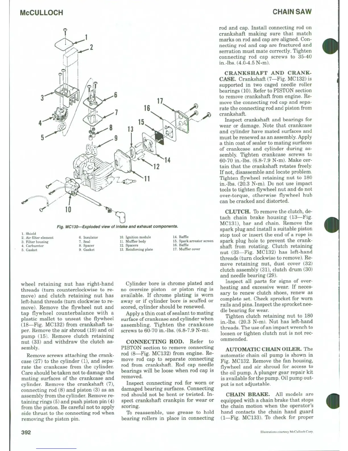
Fig. MC130—Expioded view of intake and exiiaust components.
1.
Shield
2.
Air filter element
3.
Filter housing
4.
Carburetor
5.
Gasket
6. Insulator
7.
Seal
8. Spacer
9. Gasket
10.
Ignition module
11.
Muffler body
12.
Spacers
13.
Reinforcing plate
14.
Baffle
15.
Spark arrestor screen
16.
Baffle
17.
Muffler cover
wheel retaining nut has right-hand
threads (turn counterclockwise to re-
move) and clutch retaining nut has
left-hand threads (turn clockwise to re-
move).
Remove the flywheel nut and
tap flywheel counterbalance with a
plastic mallet to unseat the flywheel
(18—Fig. MC132) from crankshaft ta-
per. Remove the air shroud (19) and oil
pump (15). Remove clutch retaining
nut (33) and withdraw the clutch as-
sembly.
Remove screws attaching the crank-
case (27) to the cylinder (1), and sepa-
rate the crankcase from the cylinder.
Care should be taken not to damage the
mating surfaces of the crankcase and
cylinder. Remove the crankshaft (7),
connecting rod (8) and piston (3) as an
assembly from the cylinder. Remove re-
taining rings (5) and push piston pin (4)
from the piston. Be careful not to apply
side thrust to the connecting rod when
removing the piston pin.
Cylinder bore is chrome plated and
no oversize piston or piston ring is
available. If chrome plating is worn
away or if cylinder bore is scuffed or
scored, cylinder should be renewed.
Apply a thin coat of sealant to mating
surface of crankcase and cylinder when
assembling. Tighten the crankcase
screws to 60-70 in.-lbs. (6.8-7.9 N-m).
CONNECTING ROD. Refer to
PISTON section to remove connecting
rod (8—Fig. MC132) from engine. Re-
move rod cap to separate connecting
rod from crankshaft. Rod cap needle
bearings will be loose when rod cap is
removed.
Inspect connecting rod for worn or
damaged bearing surfaces. Connecting
rod should not be bent or twisted. In-
spect crankshaft crankpin for wear or
scoring.
To reassemble, use grease to hold
bearing rollers in place in connecting
rod and cap. Install connecting rod on
crankshaft making sure that match
marks on rod and cap are aligned. Con-
necting rod and cap are fractured and
serration must mate correctly. Tighten
connecting rod cap screws to 35-40
in.-lbs.
(4.0-4.5 N-m).
CRANKSHAFT AND CRANK-
CASE.
Crankshaft (7—Fig. MC132) is
supported in two caged needle roller
bearings (10). Refer to PISTON section
to remove crankshaft from engine. Re-
move the connecting rod cap and sepa-
rate the connecting rod and piston from
crankshaft.
Inspect crankshaft and bearings for
wear or damage. Note that crankcase
and cylinder have mated surfaces and
must be renewed as an assembly. Apply
a thin coat of sealer to mating surfaces
of crankcase and cylinder during as-
sembly. Tighten crankcase screws to
60-70 in.-lbs. (6.8-7.9 N-m). Make cer-
tain that the crankshaft rotates freely.
If not, disassemble and locate problem.
Tighten flywheel retaining nut to 180
in.-lbs.
(20.3 N«m). Do not use impact
tools to tighten flywheel nut and do not
over-torque, otherwise flywheel hub
can be cracked and distorted.
CLUTCH. To remove the clutch, de-
tach chain brake housing (13—Fig.
MC131), bar and chain. Remove the
spark plug and install a suitable piston
stop tool or insert the end of a rope in
spark plug hole to prevent the crank-
shaft from rotating. Clutch retaining
nut (33—Fig. MC132) has left-hand
threads (turn clockwise to remove). Re-
move retaining nut, dust cover (32)
clutch assembly (31), clutch drum (30)
and needle bearing (29).
Inspect all parts for signs of over-
heating and excessive wear. If neces-
sary to renew clutch shoes, renew as
complete set. Check sprocket for worn
rails and
pins.
Inspect the sprocket nee-
dle bearing for wear.
Tighten clutch retaining nut to 180
in.-lbs.
(20.3 N-m). Nut has left-hand
threads. The use of an impact wrench to
loosen or tighten clutch nut is not rec-
ommended.
AUTOMATIC CHAIN OILER. The
automatic chain oil pump is shown in
Fig. MC132. Remove the fan housing,
fljrwheel and air shroud for access to
the oil pump. A plunger gear repair kit
is available for the pump. Oil pump out-
put is not adjustable.
CHAIN BRAKE. All models are
equipped with a chain brake that stops
the chain motion when the operator's
hand contacts the chain hand guard
(1—Fig. MC133).
TD
check for proper
392
Illustrations courtesy McCulioch Corp.



 To Next Page