3
a
6
5
6,-
2
lnset A
14
15
1
Figure s
q$
A
7
4
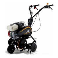
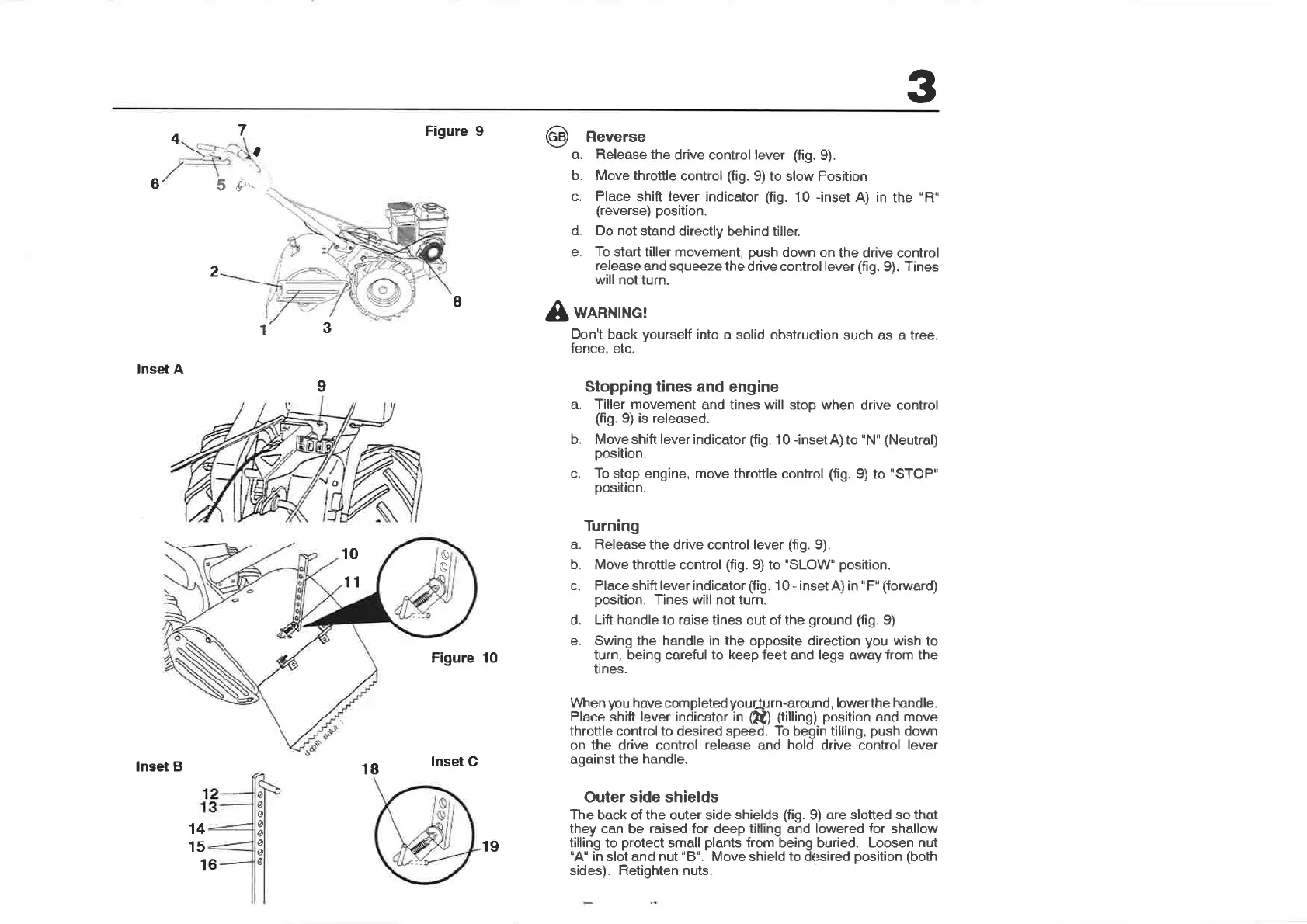
Reverse
a. Release the
drive control lever
(fig.
9).
b. Move throttle
control
(fig.
9) to slow Position
c. Place
shift
lever
indicator
(fig.
10 -inset
A) in the
"R"
(reverse)
position.
d. Do not
stand directly
behind tiller.
e.
To
start tiller movement,
push
down on
the drive control
release
and squeeze the
drive control lever
(fì9.
9). Tines
will not turn.
WARNING!
Don't back
yourself
into a solid obstruction
such as a tree,
fence,
etc.
Stopping tines
and eng¡ne
a. Tiller movement
and tines will stop when
drive control
(fig.
9) is released.
b. Moveshift leverindicator
(fig.
10
-insetA)to
"N''
(Neutral)
position.
c. To stop
engine, move throttle control (fig.
9) to
"STOP"
position.
Turning
a.
Release the drive control lever
(fig.
9).
b. Move throttle control
(fig.
9) to'SLOW"
position.
c. Place shift lever indicator (fig.
1 0
-
inset A) in
"
F"
(forward)
position.
Tines will not turn.
d. Lift handle to raise tines out of the
ground (fig.
9)
e.
Swing the handle in the
opposite
direction
you
wish to
turn, being careful to keep feet and legs away from the
tines.
Vl/hen
¡rcu
have completed
yourlJ
I¡¡-¿round,
lowerthe handle.
Place shift lever indicator in
(kù (tilling)
position
and
move
throttle control to desired speed. To begin tilling,
push
down
on the drive control
release
and hold drive control
lever
against
the handle.
Outer side shields
The back of the outer side
shields (fig.
9) are
slotted so that
they
can
be
raised for deep tilling and lowered for shallow
tilling to
protect
small
plants
from being buried. Loosen
nut
"A"
in
slot and nut
"8".
Move shield
to
d sired
position
(both
sides). Retìghten nuts.
I
3
1
9
o
10
11
Figure 10
ø
ø
ø
ø
ø
t
e
lnset B
18
lnset C
19
 Loading...