23
3
1
2
8
6
4
5
3
7
Inset A
Fig ure 9
9
Inset B
19
18
Inset C
Figure 10
10
11
depth_stake_2
17
16
12
13
14
15
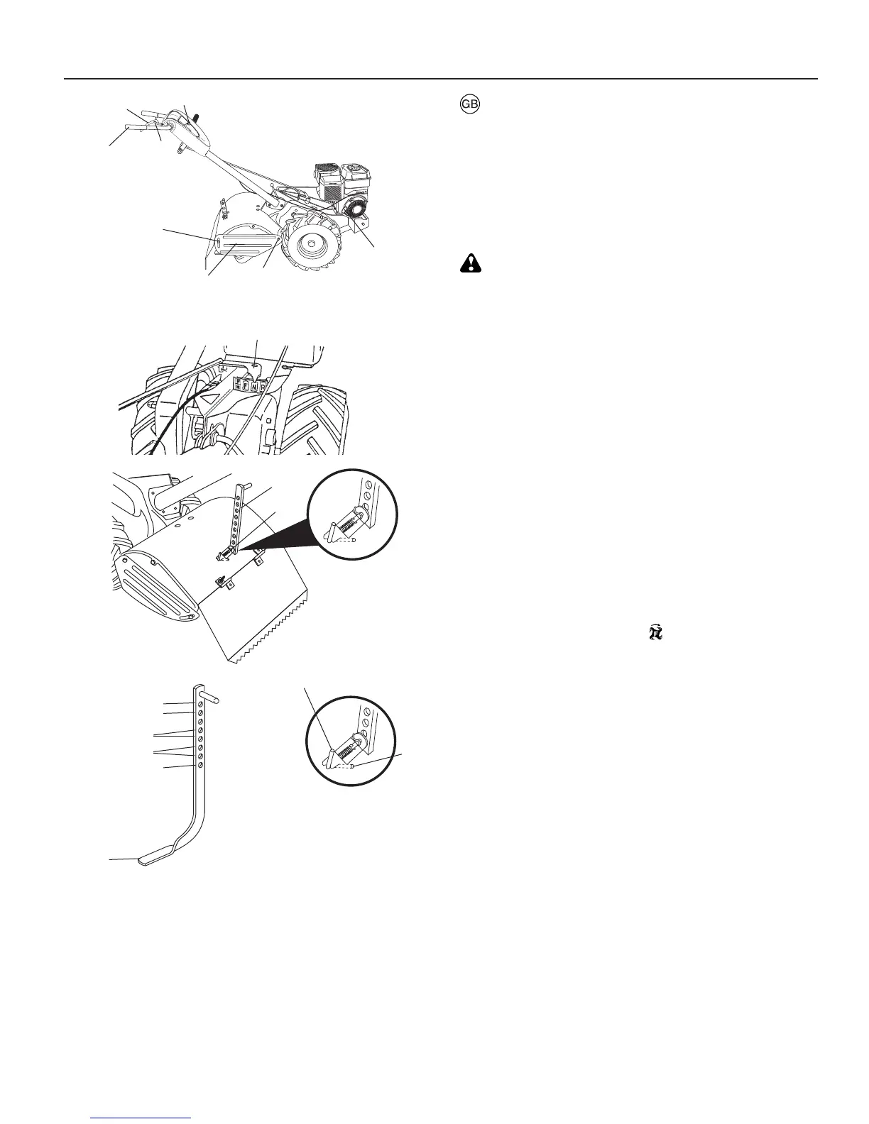
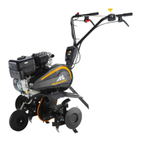
1. Outer side shield
2. Nut "A"
3. Nut "B"
4. Drive control lever
5. Drive control release
6. Handle
7. Throttle control
8. Starter handle
9. Shift lever in di ca tor
10. Depth stake
11. Depth Stake pin
12. Transport po si tion
13. Shallowest till ing
14. Shallow tilling
15. Deep tilling
16. Deepest tilling
17. Depth stake
18. "Release" po si tion
19. "Lock" position
Reverse
a. Release the drive control lever (fig. 9).
b. Move throttle control (fig. 9) to slow Position
c. Place shift lever indicator (fig. 10 -inset A) in the "R"
(reverse) position.
d. Do not stand directly behind tiller.
e. To start tiller movement, push down on the drive control
release and squeeze the drive control lever (fig. 9). Tines
will not turn.
WARNING!
Don't back yourself into a solid obstruction such as a tree,
fence, etc.
Stopping tines and engine
a. Tiller movement and tines will stop when drive control
(fig. 9) is released.
b. Move shift lever indicator (fig. 10 -inset A) to "N" (Neutral)
position.
c. To stop engine, move throttle control (fig. 9) to "STOP"
position.
Turning
a. Release the drive control lever (fig. 9).
b. Move throttle control (fig. 9) to "SLOW" po si tion.
c. Place shift lever indicator (fig. 10 - inset A) in "F" (forward)
position. Tines will not turn.
d. Lift handle to raise tines out of the ground (fig. 9)
e. Swing the handle in the opposite direction you wish to
turn, being careful to keep feet and legs away from the
tines.
When you have completed your turn-around, lower the handle.
Place shift lever in di ca tor in (
) (tilling) position and move
throttle control to desired speed. To begin tilling, push down
on the drive control release and hold drive control lever
against the handle.
Outer side shields
The back of the outer side shields (fig. 9) are slotted so that
they can be raised for deep tilling and lowered for shallow
tilling to protect small plants from being buried. Loosen nut
"A" in slot and nut "B". Move shield to desired position (both
sides). Retighten nuts.
Transporting
a. Lower the depth stake to its lowest position and insert
the depth stake pin in the topmost hole.
b. Place shift lever indicator (fig. 10 inset A) in "F" (foward)
position for transporting.
c. To start tiller movement, push down on the drive control
release and squeeze the drive control lever (fig. 9). Tines
will not turn.
d. Move throttle control (fig. 9) to desired speed.