PUMP
OPERATION
BURNER
OPERATION
FROM BURNER OR ALARM
CONTROL CIRCUIT
TO ALARM
CONTROL CIRCUIT
TO BURNER
CONTROL CIRCUIT
FROM PUMP UP
CONTROL CIRCUIT
TO PUMP UP
CONTROL CIRCUIT
NEUTRAL
HOT
BCOM
BNC
BNO
PCOM
PNC
PNO
N
H
g
f
e
d
c
b
a
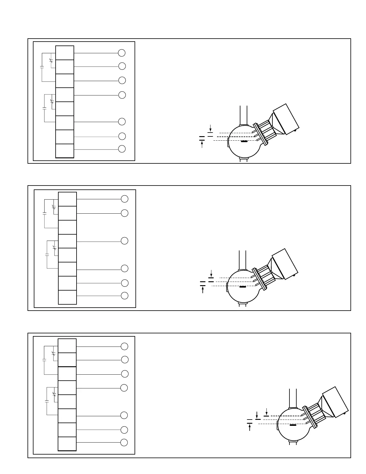
• Connect wire “a” from power supply to terminal “H”.
• Connect wire “b” from neutral supply to terminal “N”.
• Connect wire “c” from pump control circuit to terminal “PNO”.
• Connect wire “d” from pump control circuit to terminal “PCOM”.
• Connect wire “e” from burner control circuit to terminal “BNO”.
• Connect wire “f” from alarm control circuit to terminal “BNC”.
• Connect wire “g” from burner or alarm control circuit to
terminal “BCOM”.
WIRING DIAGRAMS
Low Water Cut-Off, Alarm and Pump Up Control
PUMP 1
OPERATION
PUMP 2
OPERATION
FROM PUMP #1
CONTROL CIRCUIT
FROM PUMP #2
CONTROL CIRCUIT
TO PUMP #2
CONTROL CIRCUIT
TO PUMP #1
CONTROL CIRCUIT
NEUTRAL
HOT
BCOM
BNC
BNO
PCOM
PNC
PNO
N
H
f
e
d
c
b
a
• Connect wire “a” from power supply to terminal “H”.
• Connect wire “b” from neutral supply to terminal “N”.
• Connect wire “c” from pump #1 control circuit to terminal “PNO”.
• Connect wire “d” from pump #1 control circuit to terminal “PCOM”.
• Connect wire “e” from pump #2 control circuit to terminal “BNC”.
• Connect wire “f” from pump #2 control circuit to terminal “BCOM”.
Dual Pump Control
VALVE
SPRING
CLOSED
BURNER
OPERATION
VALVE
DRIVE
TO OPEN
• Connect wire “a” from power supply to terminal “H”.
• Connect wire “b” from neutral supply to terminal “N”.
• Connect wire “c” from valve control circuit to terminal “PNO”.
• Connect wire “d” from valve control circuit to terminal “PCOM”
• Connect wire “e” from burner
control circuit to terminal “BNO”.
• Connect wire “f” from alarm
control circuit to terminal “BNC”.
• Connect wire “g” from burner
or alarm control circuit to
terminal “BCOM”.
Motorized Valve and Low Water Cut-Off
FROM VALVE
CONTROL CIRCUIT
TO VALVE
CONTROL CIRCUIT
NEUTRAL
HOT
BCOM
BNC
BNO
PCOM
PNC
PNO
N
H
d
c
b
a
FROM BURNER OR ALARM
CONTROL CIRCUIT
TO ALARM
CONTROL CIRCUIT
TO BURNER
CONTROL CIRCUIT
g
f
e
 Loading...